Supercharge Your Innovation With Domain-Expert AI Agents!

Plate perforating device capable of automatically controlling clamping

A punching device and plate technology, which is applied in the field of plate processing, can solve the problems of reduced production efficiency, unfavorable production, and poor stabilization effect, and achieve the effects of high accuracy and precision, improved production efficiency, and high stabilization effect

Inactive Publication Date: 2018-02-16
南宁市博腾安防科技有限公司
View PDF14 Cites 0 Cited by
  • Summary
  • Abstract
  • Description
  • Claims
  • Application Information

AI Technical Summary

Problems solved by technology

[0002] In the modern industrial production process, in order to improve the stability of the plate processing and prevent the plate from shifting during the plate punching process, the plate is often clamped by a clamp. The traditional punching and fixing mechanism needs to be manually fixed, which is time-consuming and laborious. The stability effect is poor, and deviations are easy to occur. The accuracy and precision of drilling cannot be well guaranteed, resulting in low production efficiency and low pass rate of workpiece products, which greatly reduces production efficiency and is not conducive to production.

Method used


Image

  • Plate perforating device capable of automatically controlling clamping
  • Plate perforating device capable of automatically controlling clamping
  • Plate perforating device capable of automatically controlling clamping

Examples


Embodiment Construction

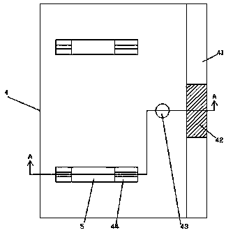
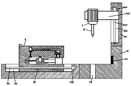
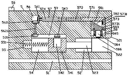
[0029] Such as Figure 1-Figure 9As shown, a kind of plate punching device with automatic control and clamping of the present invention includes a body 4, and first sliding grooves 44 are symmetrically arranged on the front and rear top end surfaces of the body 4, and each of the first sliding grooves 44 slides A clamping mechanism 5 whose top protrudes out of the top end surface of the body 4 is mated and connected, and a first threaded hole 51 extending left and right is provided inside the clamping mechanism 5 in the first slide groove 44 , and the first A first sliding cavity 54 is provided in the clamping mechanism 5 above the threaded hole 51, and the top of the first sliding cavity 54 is connected with a first transmission cavity 53, and the first sliding cavity 54 is slidably connected with Sliding block 541, the clamping mechanism 5 on the right side of the first sliding cavity 54 is provided with a clamping sliding groove 52, and a pushing block 522 is slidably conne...


PUM


Abstract

The invention discloses a plate perforating device capable of automatically controlling clamping. The plate perforating device capable of automatically controlling clamping comprises a machine body, wherein first sliding grooves are symmetrically formed in the end surfaces of the front top and rear top of the machine body; the interior of each first sliding groove is connected to a clamping mechanism with the top sticking out of the end surface of the top of the machine body in a sliding fit manner; a first screw hole which extends left and right is formed in the clamping mechanism located inthe first sliding groove; a first sliding cavity is formed in the clamping mechanism located above the first screw hole; a first transmission cavity is formed in the top of the first sliding cavity ina connection manner; the interior of the first sliding cavity is in slip connection with a sliding block; a clamping sliding groove is formed in the end surface of the right side of the clamping mechanism located at the right side of the first sliding cavity; the interior of the clamping sliding groove is in slip connection with a push block; a locking motor is fixedly arranged in the end surfaceof the top of the sliding bock; the top of the locking motor is connected to a first conical wheel extending to the interior of the first transmission cavity in a matching manner; and a second transmission cavity is arranged in the clamping mechanism located above the left side of the first transmission cavity. The plate perforating device capable of automatically controlling clamping is simple in structure, time-saving and labor-saving, is less likely to cause a deviation and improves production efficiency.

Description

technical field [0001] The invention relates to the technical field of plate processing, in particular to a plate punching device with automatic clamping control. Background technique [0002] In the modern industrial production process, in order to improve the stability of the plate processing and prevent the plate from shifting during the plate punching process, the plate is often clamped by a clamp. The traditional punching and fixing mechanism needs to be manually fixed, which is time-consuming and laborious. The stabilization effect is poor, deviations are easy to occur, and the accuracy and precision of drilling cannot be well guaranteed, resulting in low production efficiency and low pass rate of workpiece products, which greatly reduces production efficiency and is not conducive to production. Contents of the invention [0003] The technical problem to be solved by the present invention is to provide a plate punching device with automatic clamping control, which ca...

Claims


Application Information

Patent Timeline
IPC IPC(8): B26D7/04B26F1/16
CPCB26D7/04B26F1/16
Inventor 何纪全
Owner 南宁市博腾安防科技有限公司
Features
  • R&D
  • Intellectual Property
  • Life Sciences
  • Materials
  • Tech Scout
  • Unparalleled Data Quality
  • Higher Quality Content
  • 60% Fewer Hallucinations
Learn More