Charging device for new-energy vehicle

A new energy vehicle and charging device technology, applied in electric vehicle charging technology, charging stations, coupling devices, etc., can solve the problems affecting the normal charging of electric vehicles, the danger of electric shock to the charging head, and the poor safety protection, etc., and achieves convenient installation and maintenance. The effect of safe and stable operation and improved safety

Active Publication Date: 2017-08-29
建德市万家电器电缆有限公司
View PDF6 Cites 53 Cited by
  • Summary
  • Abstract
  • Description
  • Claims
  • Application Information

AI Technical Summary

Problems solved by technology

[0003] However, the use of electric vehicles is inseparable from the electric vehicle charging device. The first power supply hole on the traditional charging device is all exposed, and the first power supply hole has already It is in the energized state, which will easily cause people to get an electric shock when plugging and unplugging the charging head of the electric vehicle, and there is a relatively large safety hazard, and the charging head of the existing electric vehicle is generally engaged in the first power supply hole and exposed Outside the charging device, in the absence of a protective device, the charging head is easy to be unplugged intentionally by others or kicked off the charging head due to accidental kicking and hitting, and it is easy to kick off the charging head and break away from the first power supply hole of the charging device. The safety protection is poor, which affects the electric vehicle. normal charging

Method used


Image

  • Charging device for new-energy vehicle
  • Charging device for new-energy vehicle
  • Charging device for new-energy vehicle

Examples


Embodiment Construction

[0025] The preferred embodiments of the present invention will be described in detail below in conjunction with the accompanying drawings, so that the advantages and features of the present invention can be more easily understood by those skilled in the art, so as to define the protection scope of the present invention more clearly.

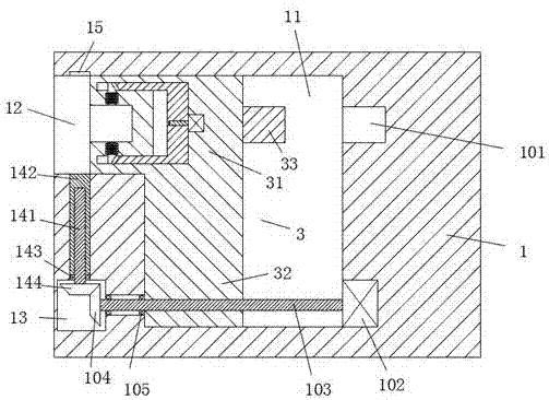
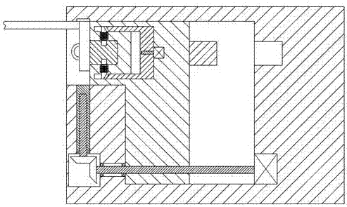
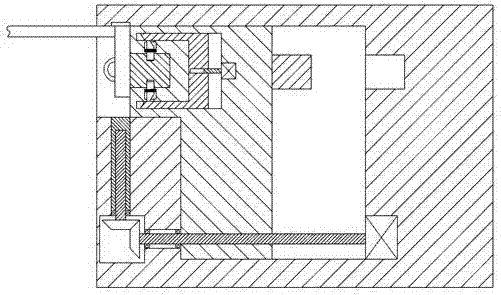
[0026] refer to Figure 1-8 The shown charging device for new energy vehicles includes a column body 1 and a sliding cavity 11 arranged in the column body 1. An insertion cavity 12 is provided on the upper left side of the column body 1, and the sliding cavity 11 can be A power supply part 3 is provided to slide left and right to connect with the charging part 2 of the new energy vehicle. The power supply part 3 includes a slide down section 32 and an up slide section 31 fixedly connected to the slide down section 32. A first power supply hole 34 is provided on the left side of the upper sliding section 31, and a power supply column 33 is provide...


PUM


Abstract

The invention discloses a charging device for a new-energy vehicle. The charging device includes a column and a sliding cavity which is arranged in the column, the upper portion of the left side of the column is provided with an insertion cavity, a power supply part for being in matched connection with a charging part of the new-energy vehicle is arranged in the sliding cavity in an up and down sliding mode, the power supply part includes a downward sliding part and an upward sliding part which is fixedly connected with the downward sliding part, the left side of the upward sliding part is provided with a first power supply hole, the right side of the upward sliding part is provided with a power supply column, and a locking part for locking the charging part is further arranged in the upward sliding part. The charging device for the new-energy vehicle is simple in overall structure, safe and stable in running, relatively low in cost, convenient to mount and maintain and easy to operate, the continuity of electric vehicle charging can be achieved, charging is prevented from being broken midway, and the charging device is suitable for popularization and usage.

Description

technical field [0001] The invention relates to the technical field of new energy vehicles, in particular to a charging device for new energy vehicles. Background technique [0002] With the development of electric vehicle technology, especially the country's continuous increase in air pollution control, electric vehicles, one of the best alternatives to traditional vehicles, are developing particularly rapidly. [0003] However, the use of electric vehicles is inseparable from the electric vehicle charging device. The first power supply hole on the traditional charging device is all exposed, and the first power supply hole has already It is in the energized state, which will easily cause people to get an electric shock when plugging and unplugging the charging head of the electric vehicle, and there is a relatively large safety hazard, and the charging head of the existing electric vehicle is generally engaged in the first power supply hole and exposed Outside the charging...

Claims


Application Information

Patent Timeline
Patent Type & Authority Applications(China)
IPC IPC(8): B60L11/18H01R13/629H01R13/639
CPCB60L53/16B60L53/31H01R13/62933H01R13/639Y02T10/70Y02T10/7072Y02T90/12Y02T90/14
Inventor 汪大海
Owner 建德市万家电器电缆有限公司
Why Eureka
Try Eureka