Charging device suitable for new energy automobile

A technology for new energy vehicles and charging devices, applied in electric vehicle charging technology, charging stations, coupling devices, etc., can solve problems such as low safety, fire, equipment damage, etc., and achieve the effect of reducing installation steps and improving installation efficiency

Inactive Publication Date: 2017-07-28
XIAOGAN BUJI ELECTRONICS COMMERCE CO LTD
View PDF0 Cites 54 Cited by
  • Summary
  • Abstract
  • Description
  • Claims
  • Application Information

AI Technical Summary

Problems solved by technology

The existing charging piles are low in safety and high in cost, and in the process of charging the electric vehicle by the charging pile, when the charging gun is accidentally charged, the charging gun is easy to loosen, causing the charging gun to become loose or loose, loose or loose. The detached charging gun will cause the electric vehicle to be unable to charge normally, and may cause safety accidents, casualties, equipment damage and even fire. In order to avoid safety accidents, it is necessary to lock the charging gun during charging. Unlock after charging, so as to ensure a completely stable normal charging work

Method used


Image

  • Charging device suitable for new energy automobile
  • Charging device suitable for new energy automobile
  • Charging device suitable for new energy automobile

Examples


Embodiment Construction

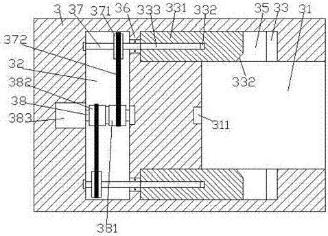
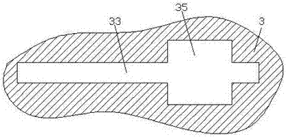
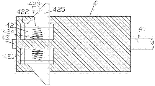
[0021] Such as Figure 1-Figure 7 As shown, a charging device suitable for new energy vehicles of the present invention includes a base 5, a charging pile body 6 installed above the base 5, a lifting block 622, and a charging device arranged in the lifting block 622. The base body 3 and the charging gun head 4, the right end surface of the charging base body 3 is provided with an insertion slot 31, and the upper and lower inner walls of the insertion slot 31 are symmetrically provided with locking slots 35, and the inside of the locking slot 35 is provided with a There are guide rail grooves 33 extending to both sides. The charging base body 3 on the left side of the insertion groove 31 is provided with a transmission cavity 32 . Between the transmission cavity 32 and the left extension of the guide rail groove 33 A partition 36 is provided, and an active rotating shaft 38 is arranged at the middle position of the transmission cavity 32. The transmission rotating shaft 37 exte...


PUM


Abstract

The invention discloses a charging device suitable for a new energy automobile. The charging device comprises a base, a charging pile body, a lifting block, a charging base body and a charging gun head, wherein the charging pile body is mounted on the base, and the charging base body is arranged in the lifting block; a plugging connecting groove is formed in the end surface of the right side of the charging base body, and lock-up grooves are formed in the upper and lower inner walls of the plugging connecting groove symmetrically; a guiding track groove extending to both sides is formed in each lock-up groove in a penetrating mode, a transmission cavity is formed in the charging base body at the left side of the plugging connecting groove, and separating plates are arranged between the transmission cavity and the extending sections of the left sides of the guiding tracks; and a driving rotating shaft is arranged at the middle position of the transmission cavity, driven rotating shafts extending to the left and right sides are arranged in the transmission cavity symmetrically and located at the upper side and the lower side of the driving rotating shaft correspondingly, the extending sections of the right sides of the driven shafts penetrate through the separating plates and are connected with the separating plates in a rotating fit mode, unlocking pushing plates are connected with the guiding track grooves internally in a sliding fit mode, threaded holes are formed in the end surfaces of the left sides of the unlocking pushing plates, and first screws are connected with the threaded holes internally in a matched mode. The charging device is simple in structure, convenient to operate, high in lock-up stability and high in safety.

Description

technical field [0001] The invention relates to the technical field of new energy vehicle charging, in particular to a charging device suitable for new energy vehicles. Background technique [0002] As a green transportation tool with broad development prospects, electric vehicles will be popularized at an extremely fast speed, and the future market prospects are also extremely huge. However, electric vehicles need to be charged through charging piles before they can continue to be used. The existing charging piles are low in safety and high in cost, and in the process of charging the electric vehicle by the charging pile, when the charging gun is accidentally charged, the charging gun is easy to loosen, causing the charging gun to become loose or loose, loose or loose. The detached charging gun will cause the electric vehicle to be unable to charge normally, and may cause safety accidents, casualties, equipment damage and even fire. In order to avoid safety accidents, it i...

Claims


Application Information

Patent Timeline
Patent Type & Authority Applications(China)
IPC IPC(8): B60L11/18H01R13/639
CPCB60L53/16H01R13/639H01R2201/26Y02T10/70Y02T10/7072Y02T90/14
Inventor 梁敏华
Owner XIAOGAN BUJI ELECTRONICS COMMERCE CO LTD
Why Eureka
Try Eureka