Welding device

A welding device and electric connector technology, applied in welding protection devices, welding equipment, welding accessories, etc., can solve the problems of loose plug connectors, susceptibility to dust accumulation, accidental electric shock risk, electric welding power supply, etc., to prevent plugging The effect of loosening and improving the stability of the power supply connection

Inactive Publication Date: 2017-08-18
杭州新罗美电子科技有限公司
View PDF0 Cites 0 Cited by
  • Summary
  • Abstract
  • Description
  • Claims
  • Application Information

AI Technical Summary

Problems solved by technology

[0002] With the continuous maturity of welding technology, the use of electric welding machines is becoming more and more extensive. In some welding factories, due to the high working voltage required by electric welding machines, the power supply body for electric welding machines is generally set separately. It is necessary to move the position from time to time to meet the welding needs in different directions. However, the existing power supply body is relatively simple. Although the power supply connection is simple, the tightness between it and the welding machine plug connector after power supply is not high. It is easy to be dragged, pulled and other external factors to make the plug connector loose, resulting in poor contact and unable to supply power for welding normally, which has great disadvantages. It also increases the risk of accidental electric shock, and there is a greater potential safety hazard

Method used


Image

  • Welding device
  • Welding device
  • Welding device

Examples


Embodiment Construction

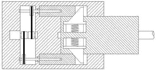
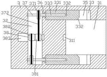
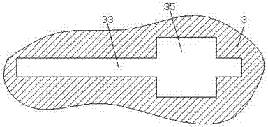
[0021] like Figure 1-Figure 7 As shown, a welding device of the present invention includes a stand 5, a body 6 installed above the stand 5, a lifting block 622, an electric block 3 and an electrical connector 4 arranged in the lifting block 622, the The inner bottom of the frame 5 is provided with a recessed groove 52, and a counterweight 53 is detachably provided in the recessed groove 52, and the bearing capacity of the frame 5 can be increased by the counterweight 53 to prevent the The pedestal 5 is too light to cause the center of gravity to be unstable and topple over. An insertion slot 31 is provided in the right end surface of the energization block, and a locking slot 35 is correspondingly provided in the upper and lower inner walls of the insertion slot 31. The inside of the locking groove 35 is provided with a sliding groove 33 extending to both sides, and the electric block 3 on the left side of the insertion groove 31 is provided with a cavity 32, and the cavity 3...


PUM


Abstract

The invention discloses a welding device, which comprises a frame, a machine body installed above the frame, a lifting block, an electrified block and an electric connector arranged in the lifting block, and the bottom of the frame is provided with a recessed slot, and the recessed slot The detachable one is equipped with a counterweight, and the right side of the power supply block is provided with an insertion slot, and the upper and lower inner walls of the insertion slot are correspondingly provided with locking slots, and the inside of the locking slot is provided with slides extending to both sides. A cavity is provided in the electrified block inserted into the left side of the slot, and a spacer is provided between the cavity and the extension section on the left side of the sliding slot. The cavities on the upper and lower sides are correspondingly provided with a second rotating shaft extended to the left and right sides. The extended section on the right side of the second rotating shaft passes through the spacer and is connected by rotation and fit, and is connected by sliding fit in the sliding groove. There is a push plate, and the left end surface of the push plate is provided with a threaded hole, and the threaded thread in the threaded hole is connected with the first threaded rod; the present invention has simple structure, convenient operation, high locking stability and high safety .

Description

technical field [0001] The invention relates to the technical field of welding, in particular to a welding device. Background technique [0002] With the continuous maturity of welding technology, the use of electric welding machines is becoming more and more extensive. In some welding factories, due to the high working voltage required by electric welding machines, the power supply body for electric welding machines is generally set separately. It is necessary to move the position from time to time to meet the welding needs in different directions. However, the existing power supply body is relatively simple. Although the power supply connection is simple, the tightness between it and the welding machine plug connector after power supply is not high. It is easy to be dragged, pulled and other external factors to make the plug connector loose, resulting in poor contact and unable to supply power for welding normally, which has great disadvantages. Also make the danger of ac...

Claims


Application Information

Patent Timeline
Patent Type & Authority Applications(China)
IPC IPC(8): B23K9/00B23K9/32
CPCB23K9/00B23K9/32B23K9/321
Inventor 马军昌
Owner 杭州新罗美电子科技有限公司
Why Eureka
Try Eureka