

Novel annular deployable truss structure
A truss structure and ring-shaped technology, applied in the direction of folding antennas, etc., can solve the problems of large folding height, large folding diameter, collision between crossbar and oblique rod, etc., and achieve the effect of reducing the folding diameter and reducing the folding height
- Summary
- Abstract
- Description
- Claims
- Application Information
AI Technical Summary
Problems solved by technology
Method used
Image

Examples
Embodiment 1
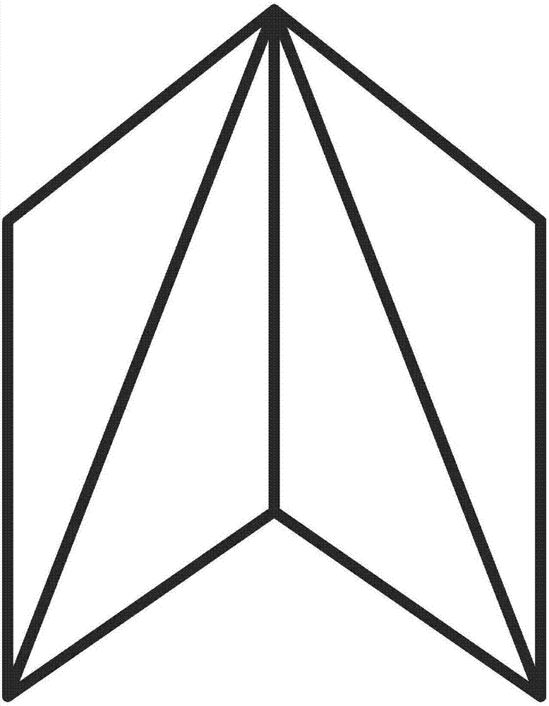
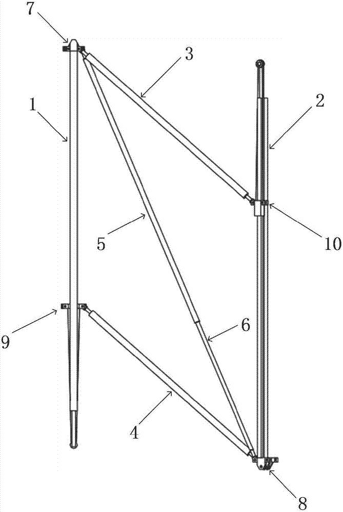
[0026] This embodiment provides a new type of ring-shaped expandable truss structure, including a plurality of parallelogram-like structural units, and adjacent parallelogram-like structural units are connected by three-point hinges and five-point hinges to form a closed ring structure; figure 2 As shown, one of the parallelogram-like structural units includes two vertical bars with the same structure, the first vertical bar 1 and the second vertical bar 2, two horizontal bars with the same structure, the first horizontal bar 3 and the second horizontal bar 4, and the first horizontal bar 3 and the second horizontal bar 4. A slanting bar 5 and a second slanting bar 6, two slanting bars, the first five-point hinge 7 and the second five-point hinge 8, two five-point hinges with the same structure, and the first three-point hinge 9 and the second three-point hinge 10 Two three-point hinges with the same structure; the upper end of the first vertical bar 1 is connected to the firs...
Embodiment 2
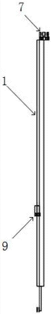
[0028] On the basis of Embodiment 1, the first vertical bar 1 and the first three-point hinge 9 , and the second vertical bar 2 and the second three-point hinge 10 are all connected by sliding pairs. The connection between the first crossbar 3 and the second three-point hinge 10 and between the second crossbar 4 and the first three-point hinge 9 are all connected by rotating pairs. Both the first vertical bar 1 and the first five-point hinge 7, and the second vertical bar 2 and the second five-point hinge 8 are connected by fixed pairs. The first slanting rod 5 and the second slanting rod 6 are connected by a sliding pair, and the two form a telescopic sleeve structure.
[0029]The novel ring-shaped expandable truss structure also includes two driving ropes, which are deployed using two driving ropes and spring drive. The first driving rope starts from the first five-point hinge 7 interface on the first vertical bar 1 and passes through the The first cross bar 3, then bypasse...
PUM
 Abstract
Description
Claims
Application Information