Elliptically interfacing gearbox
A gearbox and ellipse technology, applied in the gearbox field, can solve the problems of mechanism disengagement and low efficiency.
- Summary
- Abstract
- Description
- Claims
- Application Information
AI Technical Summary
Problems solved by technology
Method used
Image

Examples
example 1
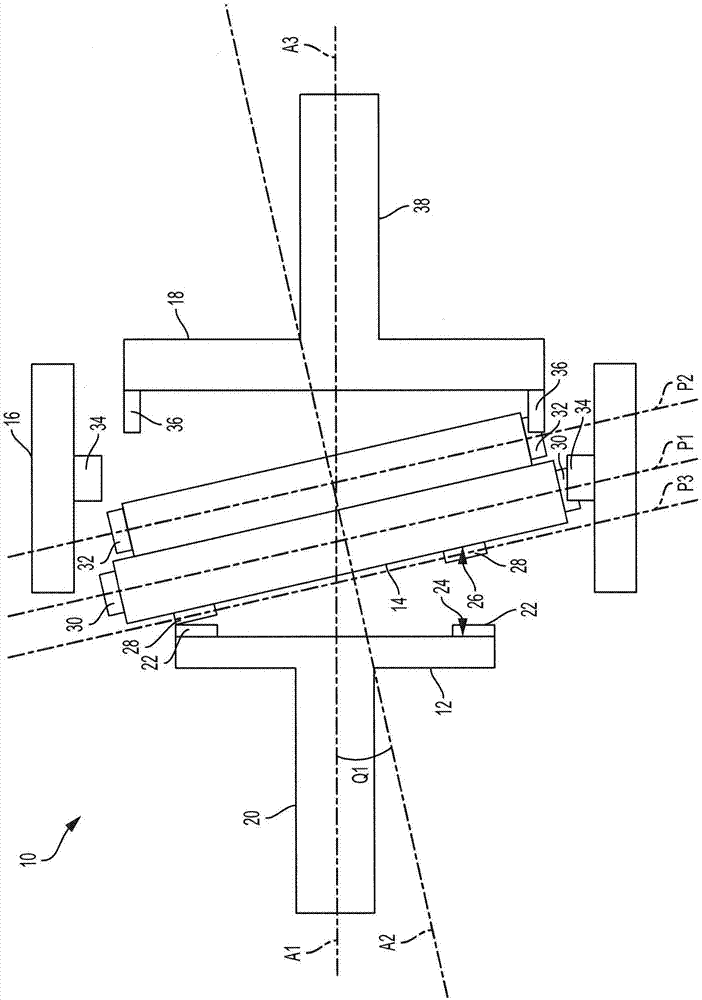
[0049] This example describes an illustrative gearbox system, see figure 1 .
[0050] figure 1 is a schematic cross-sectional view of a transmission system or gearbox, generally indicated at 10 . The transmission system 10 may include an input plate 12 , a wobble plate 14 , a stator gear 16 and an output plate 18 .
[0051] Input plate 12 may be coupled to input shaft 20 and may be configured to rotate about axis of rotation A1 . The input plate 12 is rotatable about the axis of rotation A1 in response to torque applied to the input plate by, for example, the input shaft 20 . The input plate may have a plurality of input teeth 22 arranged on an annular input surface 24 of the input plate.
[0052] The pivot plate 14 can have a pivot axis A2 which is arranged at a non-zero angle Q1 relative to the axis of rotation A1 . exist figure 1 , the angle Q1 may be exaggerated. The pivot plate 14 may have a rear face 26 and a plurality of face teeth 28 arranged on the rear face. ...
example 2
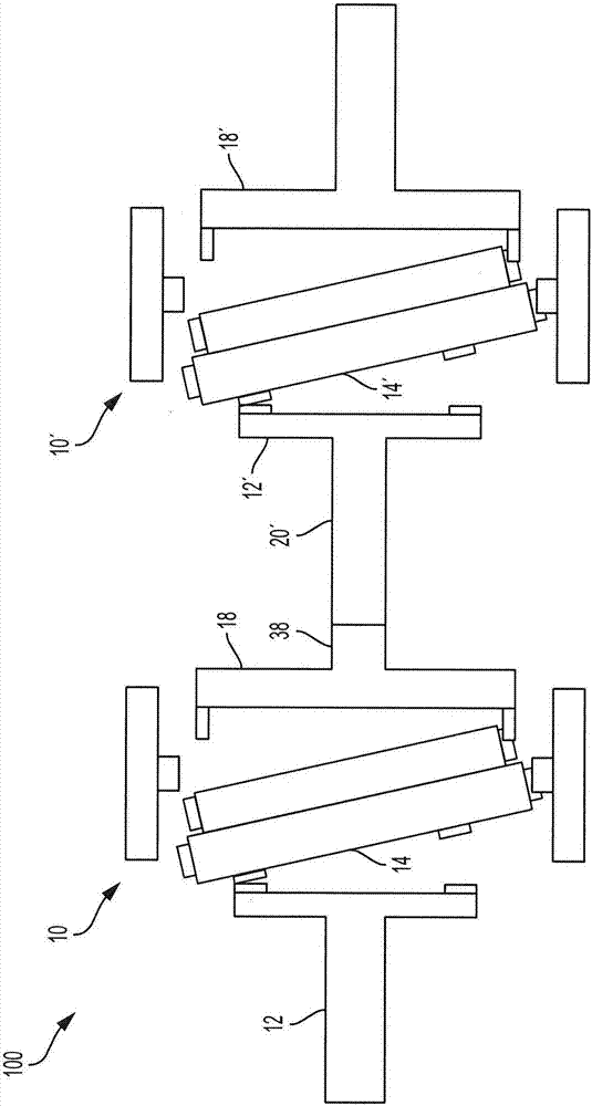
[0064] This example describes an illustrative gearbox system, see figure 2 .
[0065] figure 2 is a schematic cross-sectional view of a gearbox system, generally indicated at 100 . The gearbox system 100 may include a first gearbox system replicating Example 1 (indicated at 10) and a second gearbox system replicating Example 1 (indicated at 10'). Quoted reference numbers will be used to refer to components of the second transmission system 10' and unquoted reference numbers will be used to refer to components of the first transmission system 10. Gearbox 10 and gearbox 10' may be connected in series.
[0066] The transmission system 100 may have the output plate 18 of the transmission 10 coupled to the input plate 12' of the transmission 10'. Output plate 18 may be coupled to input plate 12' by coupling output shaft 38 to input shaft 20' such that output plate 18, output shaft 38, input shaft 20' and input plate 12' act as a single rigid unit. The transmission ratio...
example 3
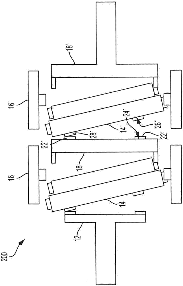
[0068] This example describes an illustrative gearbox system, see image 3 .
[0069] image 3 is a schematic cross-sectional view of a transmission system, indicated generally at 200 . The transmission system 200 may be similar in concept to the transmission system 100 described in Example 2. However, instead of connecting the output plate 18 to the input plate 12' via the output shaft 38 and the input shaft 20' as in Example 2, the transmission system 200 can dispense with the output shaft, the second input shaft and even the input plate, and have the same The output plate 18 directly engages the swing plate 14'.
[0070] The transmission system 200 may have an input plate 12 that engages with and drives rotation of the wobble plate 14 . The wobble plate 14 is engageable with the stator 16 and nutates about the stator 16 as it rotates. The wobble plate 14 is engageable with the output plate 18 and drives rotation of the output plate 18 as the wobble plate 14 nutates abo...
PUM
 Abstract
Description
Claims
Application Information
 - R&D
- Intellectual Property
- Life Sciences
- Materials
- Tech Scout
- Unparalleled Data Quality
- Higher Quality Content
- 60% Fewer Hallucinations
Browse by: Latest US Patents, China's latest patents, Technical Efficacy Thesaurus, Application Domain, Technology Topic, Popular Technical Reports.
© 2025 PatSnap. All rights reserved.Legal|Privacy policy|Modern Slavery Act Transparency Statement|Sitemap|About US| Contact US: help@patsnap.com