Automatic anchor rod mounting equipment special for tunnel and bridge construction

An automatic installation and bolting technology, applied in drilling equipment, drilling equipment and methods, construction and other directions, can solve the problems of safety, poor flexibility, and imprecise drilling in manual drilling, and achieve high labor intensity and work efficiency. High efficiency, simple structure and lightweight effect

Inactive Publication Date: 2017-08-11
王保周 +2
View PDF4 Cites 4 Cited by
  • Summary
  • Abstract
  • Description
  • Claims
  • Application Information

AI Technical Summary

Problems solved by technology

[0003] In order to solve the above-mentioned problems, the present invention provides an automatic bolt installation equipment for tunnel and bridge construction, which can solve the problem of troublesome drilling and poor flexibility of large-scale mechanical equipment in the narrow working environment existing in the bolt reinforcement process of existing tunnel and bridge construction. High consumption, manual drilling has hidden safety hazards, high labor intensity, inaccurate drilling, and low work efficiency. After the drilling is completed, the anchor rod needs to be manually installed in the drilling hole, and the operation is complicated. It can realize the tunnel bridge construction process. The function of automatic installation of medium anchor rods is simple and light in structure, suitable for various working environments, automatic conveying of anchor rods, no manual operation, no potential safety hazards, good flexibility, low consumption, accurate drilling, simple operation and work High efficiency and other advantages

Method used


Image

  • Automatic anchor rod mounting equipment special for tunnel and bridge construction
  • Automatic anchor rod mounting equipment special for tunnel and bridge construction
  • Automatic anchor rod mounting equipment special for tunnel and bridge construction

Examples


Embodiment Construction

[0022] In order to make the technical means, creative features, goals and effects achieved by the present invention easy to understand, the present invention will be further described below in conjunction with specific illustrations.

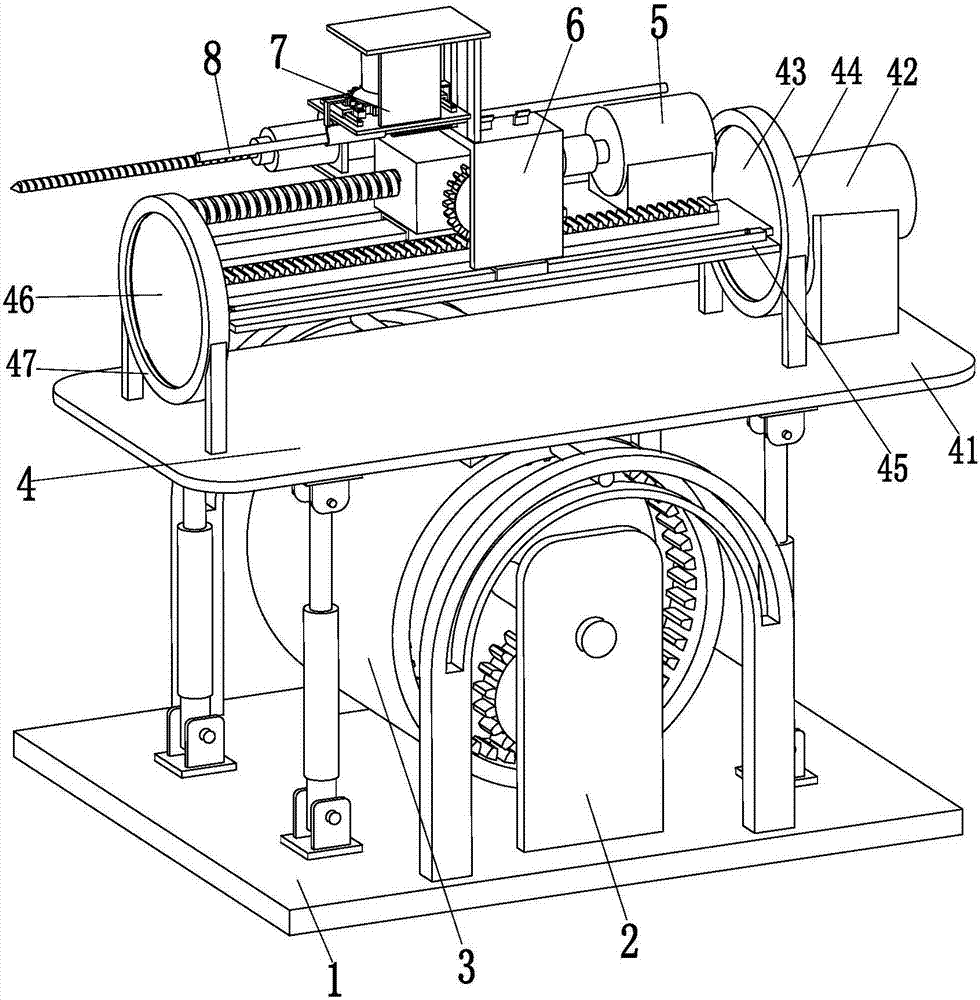
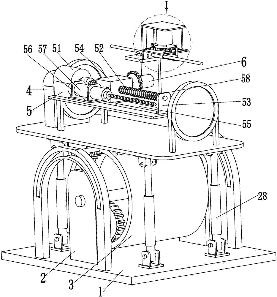
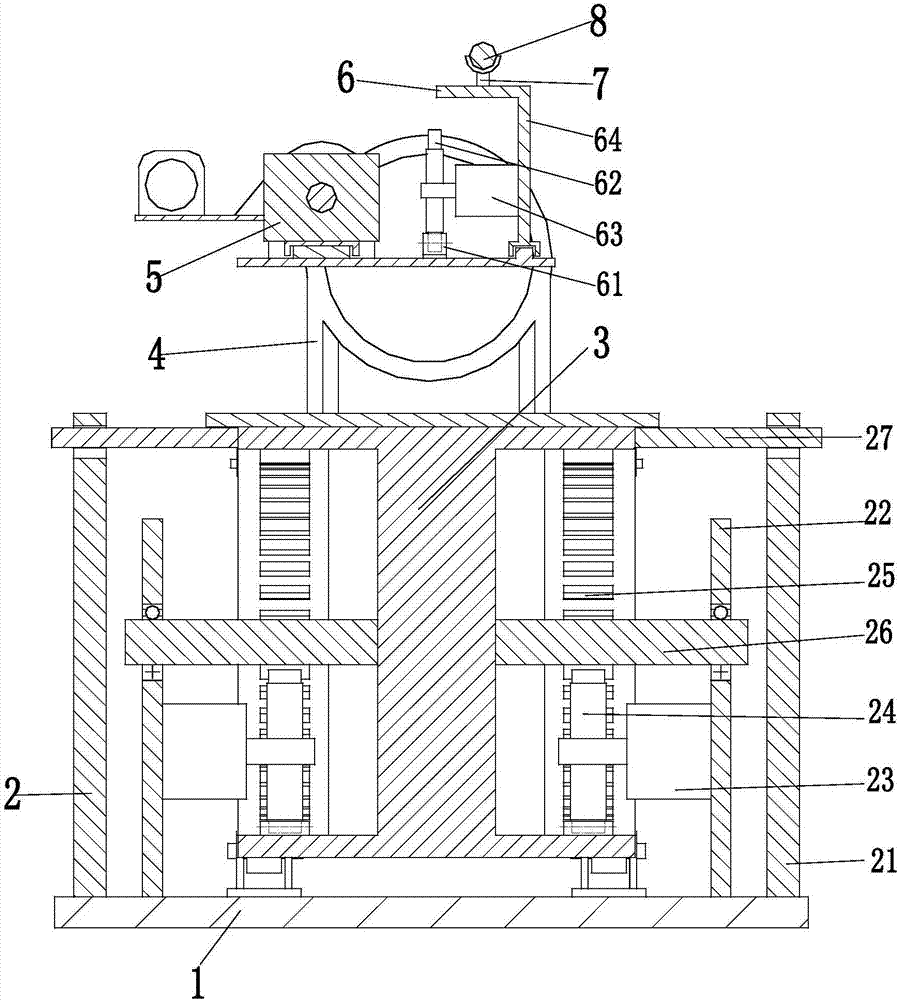
[0023] like Figure 1 to Figure 4 As shown, an automatic bolt installation equipment for tunnel bridge construction includes a base plate 1, two adjustment devices 2 are installed symmetrically on the left and right sides of the base plate 1, and an adjustment column 3 is installed between the two adjustment devices 2 through bearings. An adjustment device 2 can drive the adjustment column 3 to adjust the angle. The cross section of the adjustment column 3 is an I-shaped structure with both left and right ends indented inward. A conversion device 4 is installed on the adjustment column 3 by welding. The right end of the conversion device 4 Drilling device 5 is installed, and feed device 6 is installed on the left end of conversion device 4, and ...


PUM


Abstract

The invention relates to automatic anchor rod mounting equipment special for tunnel and bridge construction. The automatic anchor rod mounting equipment special for tunnel and bridge construction comprises a base plate. Two adjustment devices are symmetrically mounted on the base plate. An adjustment column is mounted between the two adjustment devices. A conversion device is mounted on the adjustment column. A drilling device is mounted at the right end of the conversion device. A feeding device is mounted at the left end of the conversion device. A clamping device is mounted on the feeding device. The adjustment devices, the adjustment column, the conversion device, the drilling device, the feeding device and the clamping device are used in cooperation to complete the automatic anchor rod mounting process during tunnel and bridge construction. By adoption of the automatic anchor rod mounting equipment special for tunnel and bridge construction, the problems that in the prior art, when large mechanical equipment is used in the anchor rod reinforcing process during tunnel and bridge construction, drilling in a narrow working environment is troublesome, and consumption is large; and manual drilling can cause potential safety hazards and is high in labor intensity and low in working efficiency, anchor rods need to be mounted in drilled holes manually after drilling is ended, and operation is complex can be solved; and the automatic anchor rod mounting function can be achieved in the tunnel and bridge construction process.

Description

technical field [0001] The invention relates to the technical field of mechanical equipment for tunnels and bridges, in particular to an automatic installation device for bolts specially used for tunnel and bridge construction. Background technique [0002] In the process of tunnel and bridge construction, in order to prevent the formation from being deformed, collapsed or unstable and endangering safety, one of the main support technologies for strengthening the formation is bolt reinforcement. In the existing construction process of bolts, large-scale There are two ways to install anchor rods by mechanical equipment drilling and manual drilling. Large-scale mechanical equipment drilling installation has good stability, precise drilling, and high work efficiency. However, large-scale mechanical equipment drilling is mainly suitable for relatively open sites. In the working environment, it is troublesome to drill large-scale mechanical equipment in a relatively narrow workin...

Claims


Application Information

Patent Timeline
Patent Type & Authority Applications(China)
IPC IPC(8): E02D7/00E21B7/00
CPCE02D7/00E21B7/00
Inventor 盛亚红
Owner 王保周
Why Eureka
Try Eureka