
An electric fastener installation device

A technology for installing equipment and fasteners, which is applied in the field of electric fastener installation equipment, can solve problems such as high labor intensity, potential safety hazards, and cumbersome and complicated processes, and achieve the effects of reducing labor intensity, improving work efficiency, and simple operation

Active Publication Date: 2019-12-13
ELECTRIC POWER RES INST OF GUANGDONG POWER GRID
View PDF9 Cites 0 Cited by
  • Summary
  • Abstract
  • Description
  • Claims
  • Application Information

AI Technical Summary

Problems solved by technology

[0003] In order to solve the above problems, the present invention provides an electric fastener installation device, which can solve the problem that when installing the electric clamp, personnel need to hold the clamp and then twist the nut to limit the position. The process is cumbersome and complicated, and personnel are required to install it Hand clamps are used for installation. When the personnel hold the clamps at high altitude, improper operation may cause potential safety hazards. The personnel need to take out relative tools to twist the nuts according to different specifications, and the nuts are easy to fall during installation. Long time-consuming, labor-intensive and low-efficiency problems, can realize the function of automatic installation of electric clamps, automatic limit clamps, targeted screwing for nuts of different specifications, the nuts will not fall during installation, No manual operation is required, which ensures the safety of personnel, takes less time, and has the advantages of simple operation, low labor intensity and high work efficiency.

Method used


Image

  • An electric fastener installation device
  • An electric fastener installation device
  • An electric fastener installation device

Examples


Embodiment Construction

[0028] In order to make the technical means, creative features, goals and effects achieved by the present invention easy to understand, the present invention will be further described below in conjunction with specific illustrations. It should be noted that, in the case of no conflict, the embodiments in the present application and the features in the embodiments can be combined with each other.

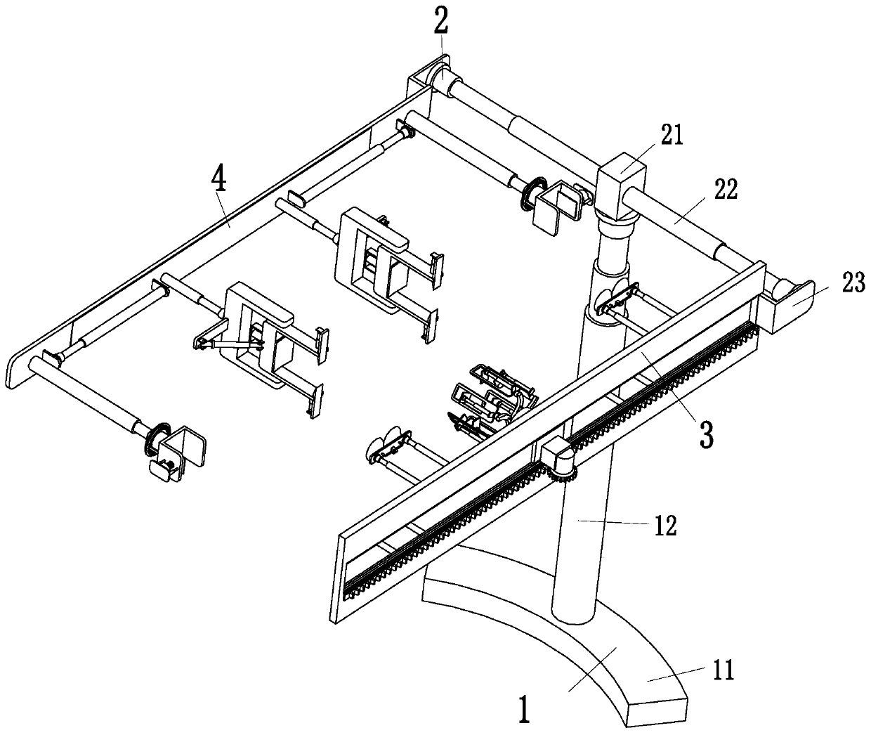
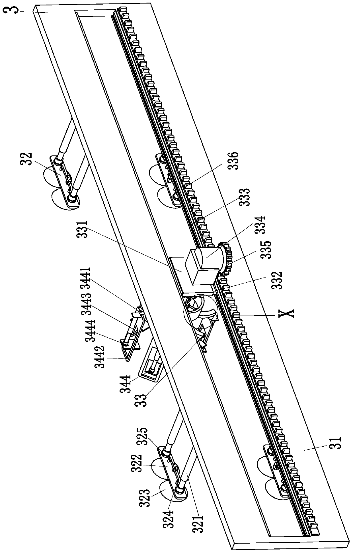
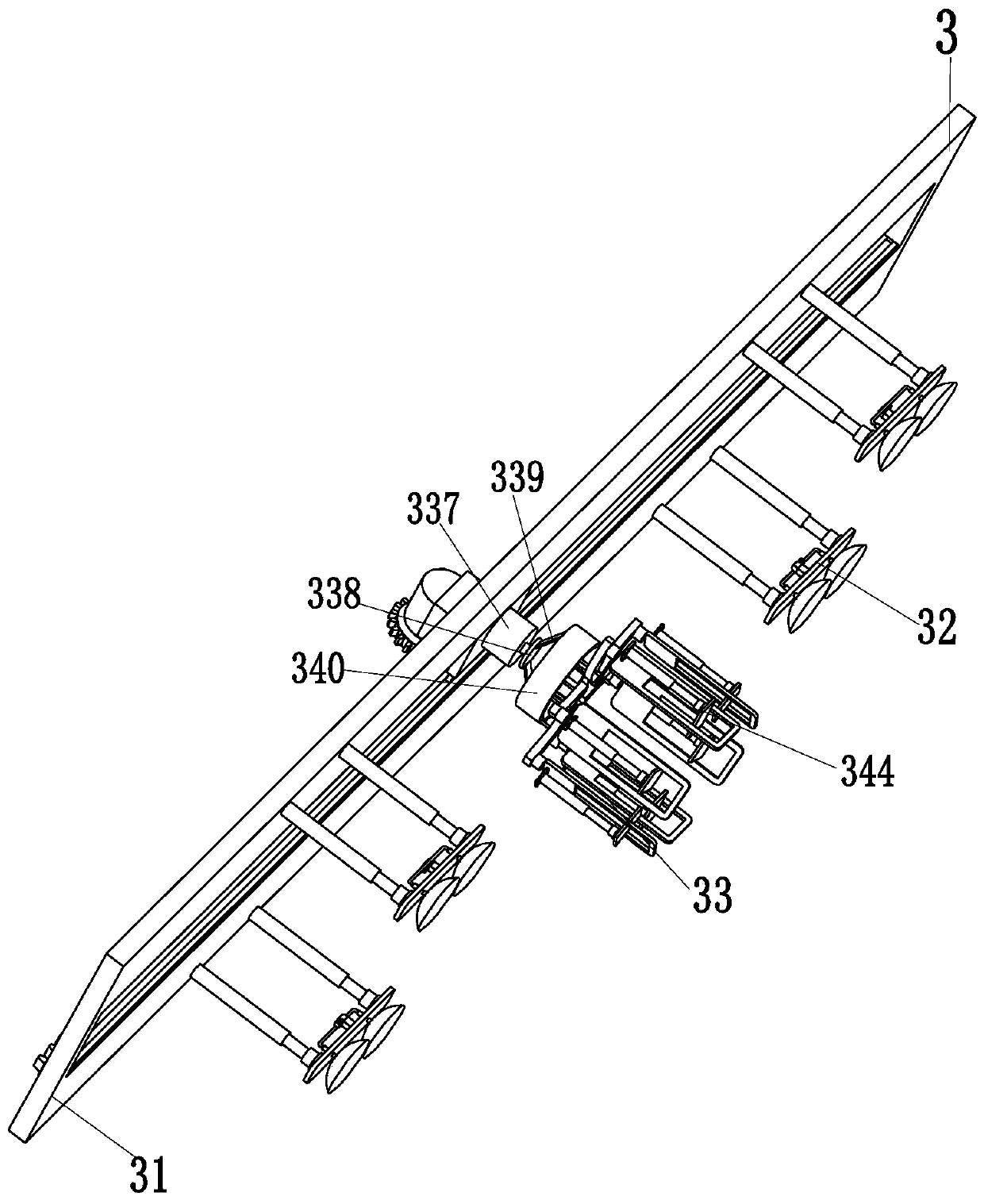
[0029] Such as Figure 1 to Figure 6 As shown, in order to achieve the above object, the present invention adopts the following technical solutions: an electric fastener installation equipment, including a support device 1, a connection device 2, a nut installation device 3 and a bolt fixing device 4, the support device 1 A connecting device 2 is installed at the upper end, a nut mounting device 3 is installed at the front end of the connecting device 2 , and a bolt fixing device 4 is installed at the rear end of the connecting device 2 .

[0030] The support device 1 includes an ar...


PUM


Abstract

The invention relates to electric power fastener mounting equipment. The electric power fastener mounting equipment includes a supporting device, a connecting device, a nut mounting device and a boltfixing device. The connecting device is installed at the upper end of the supporting device, the nut mounting device is installed at the front end of the connecting device, and the bolt fixing deviceis installed at the rear end of the connecting device. The electric power fastener mounting equipment can solve the existing problems that when an electric power clamp is installed, a personnel needsto hold the electric power clamp and then screws nuts for limiting, so that the process is tedious and complicated, during installation, the personnel needs to hold the clamp by a hand for installation, when the personnel works at high altitude with the clamp in hand, potential safety hazards are prone to occurring due to improper operations, and therefore, the personnel needs to take out corresponding tools according to different specifications of nuts for screwing; and the nuts are prone to falling off during installation, so that the process takes a long time, the labor intensity is high and the efficiency is low. According to the electric power fastener mounting equipment, the function of automatic installation of electric power clamps can be realized.

Description

technical field [0001] The invention relates to the field of electric fastener installation, in particular to an electric fastener installation equipment. Background technique [0002] The so-called hoop is a component that hugs or hoops another material with one material. It belongs to a fastener. The hoop device is composed of a hoop plate, a wing plate, a tie rib plate, a bolt and an inner liner. The hoop There are many kinds of hoops, cable hoops, utility pole hoops, cable hoops, suspension wire hoops, and stainless steel hoops are commonly used. Therefore, hoops are widely used in the power field, but the process of installing hoops is cumbersome and complicated. , how to install the hoop has become a big problem. Nowadays, it is necessary for personnel to hold the hoop and then twist the nut to limit the position. The process is cumbersome and complicated. During operation, improper operation can easily lead to potential safety hazards. Personnel need to take out rela...

Claims


Application Information

Patent Timeline
Patent Type & Authority Patents(China)
IPC IPC(8): B23P19/00B23P19/06
CPCB23P19/00B23P19/06
Inventor 张晓锋
Owner ELECTRIC POWER RES INST OF GUANGDONG POWER GRID
Learn More