Antenna device and electronic device

A technology for antenna devices and electronic equipment, which is applied in the field of communication, and can solve problems such as the inability of antenna devices to meet isolation requirements

Active Publication Date: 2017-08-11
VIVO MOBILE COMM CO LTD
View PDF7 Cites 56 Cited by
  • Summary
  • Abstract
  • Description
  • Claims
  • Application Information

AI Technical Summary

Problems solved by technology

[0003] Embodiments of the present invention provide an antenna device and electronic equipment to solve the pro

Method used


Image

  • Antenna device and electronic device
  • Antenna device and electronic device
  • Antenna device and electronic device

Examples


no. 1 example

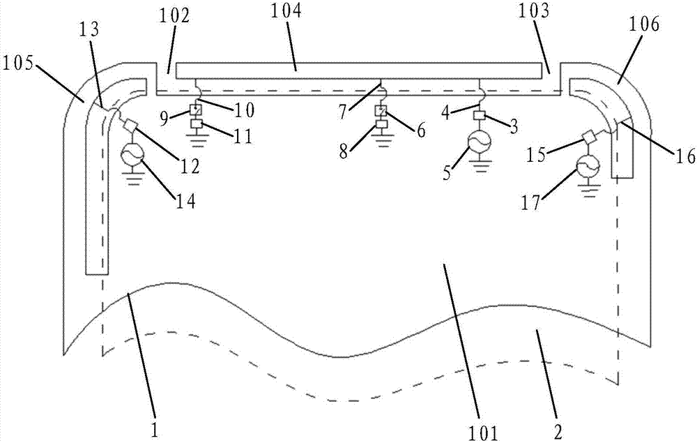
[0022] see figure 1 , the embodiment of the present invention provides an antenna device applied to an electronic device, comprising: a metal casing 1 with a slot structure, a first matching circuit 3 and a second matching circuit 12 . It should be noted that the metal casing 1 is a metal structure with a gap structure on the electronic device. For example, the metal casing 1 can be a metal battery cover, or it can be a metal frame with a gap structure composed of a metal middle frame and a screen bracket. body. The slit structure can be arranged at the upper end, lower end, left end or right end of the metal casing 1 (electronic device), and the specific position can be set according to actual design requirements, and is not specifically limited here.

[0023] Specifically, the metal casing 1 is divided into an antenna arm part and a main ground part 101 by a slot structure. The gap structure is filled with non-metallic materials.

[0024] Wherein, the antenna arm part is ...

no. 2 example

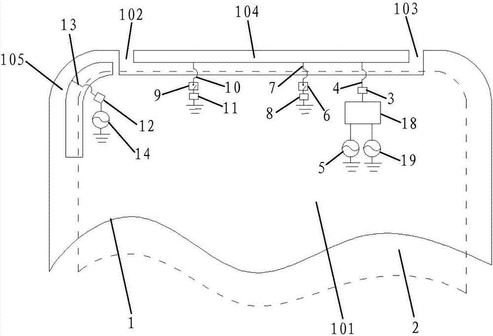
[0039] see figure 2 , the embodiment of the present invention provides an antenna device, which is applied to an electronic device, and the antenna device includes: a metal shell 1 with a slot structure, a first matching circuit 3, a second matching circuit 12, a combiner 18 and A fourth feed 19 connected to ground. It should be noted that the metal casing 1 is a metal structure with a gap structure on the electronic device. For example, the metal casing 1 can be a metal battery cover, or it can be a metal frame with a gap structure composed of a metal middle frame and a screen bracket. body. The slit structure can be arranged at the upper end, lower end, left end or right end of the metal casing 1 (electronic device), and the specific position can be set according to actual design requirements, and is not specifically limited here.

[0040] Specifically, the metal casing 1 is divided into an antenna arm part and a main ground part 101 by a slot structure. The gap structur...

no. 3 example

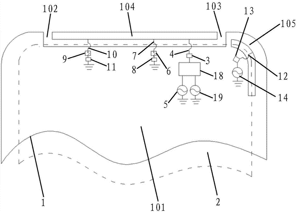
[0054] see image 3 , the embodiment of the present invention provides an antenna device, which is applied to an electronic device, and the antenna device includes: a metal shell 1 with a slot structure, a first matching circuit 3, a second matching circuit 12, a combiner 18 and A fourth feed 19 connected to ground. It should be noted that the metal casing 1 is a metal structure with a gap structure on the electronic device. For example, the metal casing 1 can be a metal battery cover, or it can be a metal frame with a gap structure composed of a metal middle frame and a screen bracket. body. The slit structure can be arranged at the upper end, lower end, left end or right end of the metal casing 1 (electronic device), and the specific position can be set according to actual design requirements, and is not specifically limited here.

[0055] Specifically, the metal casing 1 is divided into an antenna arm part and a main ground part 101 by a slot structure. The gap structure...


PUM


Abstract

The present invention discloses an antenna device and an electronic device. The antenna device comprises a metal housing with a slit structure, wherein the metal housing is divided into an antenna arm portion and a main area portion; the antenna arm portion comprises a first fracture and a second fracture, and the antenna arm portion is at least divided by the first fracture and the second fracture into: a first antenna arm located between the first fracture and the second fracture, the first antenna arm being separating from the main area portion, a second antenna arm located at the first side of the first antenna arm, the first end and the second end of the second antenna arm being connected with the main area portion, a first matching circuit, one end of the first matching circuit being connected with the first antenna arm through a first metal connection piece, the other end of the first matching circuit being earthed at least through a first feed source; and a second matching circuit, one end of the second matching circuit being connected with the second antenna arm through a second metal connection piece, and the other end thereof being earthed through a second feed source. The antenna device and the electronic device is low in contour and high isolation, satisfy carrier aggregation, and facilitate improving antenna radiation efficiency and partial space multi-antenna design.

Description

technical field [0001] The invention relates to the technical field of communications, in particular to an antenna device and electronic equipment. Background technique [0002] Currently, battery covers of electronic devices are mostly made of metal. Since the design of the slot antenna is related to the position of the slot and the display screen, the projection area of ​​the display screen on the battery cover cannot cover the projection of the radiation slot. With the ever-increasing display-to-body ratio, the profile of the antenna arm gradually narrows, resulting in an increased figure of merit and narrowed bandwidth. In the case of low profile requirements and increasing proportion of display screens, GPS / WIFI common antennas and 2G / 3G / 4G communication antennas have low radiation efficiency, and 2G / 3G / 4G communication antennas cannot meet carrier aggregation requirements. At the same time, the isolation between the multi-antenna system and the MIMO antenna system ca...

Claims


Application Information

Patent Timeline
IPC IPC(8): H01Q1/52H01Q1/50H01Q1/22H01Q5/28H01Q5/328
CPCH01Q1/22H01Q1/50H01Q1/521H01Q5/28H01Q5/328
Inventor 侯梓鹏陈玉稳
Owner VIVO MOBILE COMM CO LTD
Why Eureka
Try Eureka