A kind of antenna device and electronic equipment
A technology for antenna devices and electronic equipment, which is applied in the field of communication, and can solve problems such as the inability of antenna devices to meet isolation requirements
- Summary
- Abstract
- Description
- Claims
- Application Information
AI Technical Summary
Problems solved by technology
Method used
Image
Examples
no. 1 example
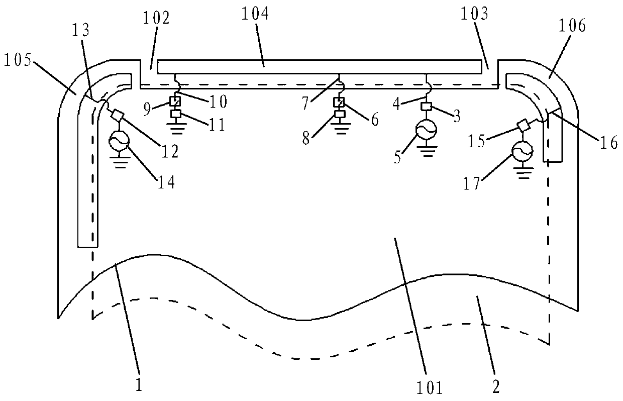
[0022] see figure 1 , the embodiment of the present invention provides an antenna device applied to an electronic device, comprising: a metal casing 1 with a slot structure, a first matching circuit 3 and a second matching circuit 12 . It should be noted that the metal casing 1 is a metal structure with a gap structure on the electronic device. For example, the metal casing 1 can be a metal battery cover, or it can be a metal frame with a gap structure composed of a metal middle frame and a screen bracket. body. The slit structure can be arranged at the upper end, lower end, left end or right end of the metal casing 1 (electronic device), and the specific position can be set according to actual design requirements, and is not specifically limited here.
[0023] Specifically, the metal casing 1 is divided into an antenna arm part and a main ground part 101 by a slot structure. The gap structure is filled with non-metallic materials.
[0024] Wherein, the antenna arm part is ...
no. 2 example
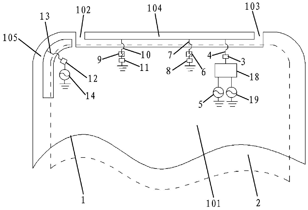
[0039] see figure 2 , the embodiment of the present invention provides an antenna device, which is applied to an electronic device, and the antenna device includes: a metal shell 1 with a slot structure, a first matching circuit 3, a second matching circuit 12, a combiner 18 and A fourth feed 19 connected to ground. It should be noted that the metal casing 1 is a metal structure with a gap structure on the electronic device. For example, the metal casing 1 can be a metal battery cover, or it can be a metal frame with a gap structure composed of a metal middle frame and a screen bracket. body. The slit structure can be arranged at the upper end, lower end, left end or right end of the metal casing 1 (electronic device), and the specific position can be set according to actual design requirements, and is not specifically limited here.
[0040] Specifically, the metal casing 1 is divided into an antenna arm part and a main ground part 101 by a slot structure. The gap structur...
no. 3 example
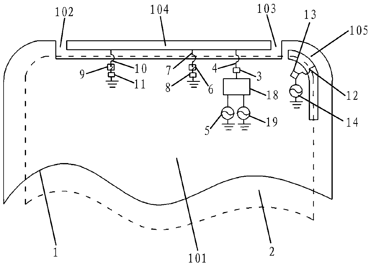
[0054] see image 3 , the embodiment of the present invention provides an antenna device, which is applied to an electronic device, and the antenna device includes: a metal shell 1 with a slot structure, a first matching circuit 3, a second matching circuit 12, a combiner 18 and A fourth feed 19 connected to ground. It should be noted that the metal casing 1 is a metal structure with a gap structure on the electronic device. For example, the metal casing 1 can be a metal battery cover, or it can be a metal frame with a gap structure composed of a metal middle frame and a screen bracket. body. The slit structure can be arranged at the upper end, lower end, left end or right end of the metal casing 1 (electronic device), and the specific position can be set according to actual design requirements, and is not specifically limited here.
[0055] Specifically, the metal casing 1 is divided into an antenna arm part and a main ground part 101 by a slot structure. The gap structure...
PUM
 Abstract
Description
Claims
Application Information
 - R&D
- Intellectual Property
- Life Sciences
- Materials
- Tech Scout
- Unparalleled Data Quality
- Higher Quality Content
- 60% Fewer Hallucinations
Browse by: Latest US Patents, China's latest patents, Technical Efficacy Thesaurus, Application Domain, Technology Topic, Popular Technical Reports.
© 2025 PatSnap. All rights reserved.Legal|Privacy policy|Modern Slavery Act Transparency Statement|Sitemap|About US| Contact US: help@patsnap.com


