Cooking stove

A technology for cooking and stoves, applied in the field of outdoor cooking stoves, can solve problems such as incompatibility of solid fuel blocks, and achieve the effect of efficient operation

Inactive Publication Date: 2017-08-18
STANDARD BRANDS (UK) LTD
View PDF6 Cites 2 Cited by
  • Summary
  • Abstract
  • Description
  • Claims
  • Application Information

AI Technical Summary

Problems solved by technology

Unfortunately, however, the inherently vigorous combustion of solid fuel blocks makes solid fuel blocks incompatible with this method

Method used


Image

  • Cooking stove
  • Cooking stove
  • Cooking stove

Examples


Embodiment Construction

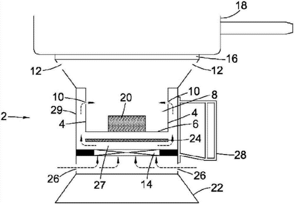
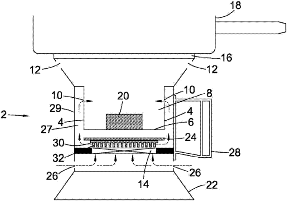
[0042] According to a first aspect, the present invention provides a cooking stove comprising: a combustion chamber delimited by a wall and a bottom, the wall having one or more air inlets; and a fan, the The fan is configured to force air into the combustion chamber through one or more air inlets; characterized in that the one or more air inlets in the wall of the combustion chamber are positioned at least 30 mm from the bottom. The one or more air inlets in the wall of the combustion chamber may be positioned at least 35mm, preferably 40mm, from the bottom. In the case of larger cookers, the one or more air inlets may be positioned at least 70mm or at least 110mm from the bottom.

[0043] By combustion chamber we mean the part of a cooking stove where the combustion of fuel takes place. The combustion chamber is delimited by a wall and a bottom, and the height of the combustion chamber extends between the bottom of the combustion chamber and the top of the wall, said top ge...


PUM


Abstract

A cooking stove (2) comprising a fan (14) configured to force air into a combustion chamber (8) through air inlets (10) in the walls (4) of the combustion chamber (8). The air inlets (10) are positioned at least 30mm from the base (6) of the combustion chamber (8) and direct the forced air to the headspace above the fuel (20). Clean combustion of high energy fuels can be achieved by the cooking stove (2).

Description

technical field [0001] The present technology relates to cooking stoves, and in particular, to lightweight, efficient, and portable outdoor cooking stoves primarily used by those engaged in general camping or other outdoor recreational activities or by entertaining large groups of people or humanitarian purposes. The cooking range is designed to efficiently utilize solid fuel pellets and minimize soot deposits on the cooking vessel. Background technique [0002] Outdoor enthusiasts and military personnel who often carry their own equipment for extended periods of time need their equipment to be lightweight and suitable for compact storage. Environments are often encountered that do not provide fuel sources such as dry wood, requiring prudent persons to also carry their own fuel. Stoves have been developed that can be used with solid fuel blocks. In addition to being used by outdoor enthusiasts and military personnel, solid fuel blocks are also well suited for humanitarian...

Claims


Application Information

Patent Timeline
Patent Type & Authority Applications(China)
IPC IPC(8): A47J37/07F24B1/20F24C1/16
CPCA47J37/0754F24B1/202F24C1/16F24C1/02F24C1/06F23D3/02
Inventor 埃里克·丹尼斯·巴福德
Owner STANDARD BRANDS (UK) LTD
Why Eureka
Try Eureka