Waterproof electronic equipment unit

An electronic equipment, waterproof technology, applied in the direction of electrical equipment structural parts, electrical components, electrical equipment shell/cabinet/drawer, etc. The device 42 has problems such as poor heat dissipation characteristics, and achieves the effects of not being in direct contact with water, suppressing effective space, and having a small and cheap structure.

Active Publication Date: 2017-08-22
MITSUBISHI ELECTRIC CORP
View PDF6 Cites 1 Cited by
  • Summary
  • Abstract
  • Description
  • Claims
  • Application Information

AI Technical Summary

Problems solved by technology

[0014] Although the "substrate storage case for electronic control device" of the above-mentioned Patent Document 1 has the effect of improving the absorption capacity of radiant heat generated from the first substrate surface 43 side of the circuit substrate 40 by the low plane portion 21 of the cover plate 20, However, the external control of the low plane part 21 is not effectively used, so it is impossible to expect to reduce the external dimensions of the entire housing
[0015] In addition, since the heat generated by the heating element 43a is transferred to the side of the base 30, when the temperature on the side of the base 30 is higher than that on the side of the cover 20, there is a problem that the heat dissipation characteristic of the heating element 43a is not good.
[0016] In addition, there is no discussion on the installation position of the waterproof filter layer for protecting the sealing materials 11a-11c coated between the cover plate 20, the base 30, and the connecting shell 41.
[0017] The "casing and method of assembling the housing" of the above-mentioned Patent Document 2 is intended to obtain an improved waterproof seal between the cover plate 30A and the base (casing) 20A constituting the housing in which the circuit board is hermetically accommodated. Small and cheap casing, but since the heat generated by the heating element 42 is transferred to the side of the base (housing) 20A, when the temperature on the side of the base (housing) 20A is higher than that on the side of the cover plate 30A, The heat dissipation characteristics of the heat generating components 42 will become poor, and the effect of transferring heat to the cover plate 30A cannot be obtained. Instead, the heat dissipation fins 23A are arranged adjacent to the high components, that is, the connection housings 24Aa, 24Ab, resulting in The overall structure size becomes larger

Method used


Image

  • Waterproof electronic equipment unit
  • Waterproof electronic equipment unit
  • Waterproof electronic equipment unit

Examples


Embodiment approach 1

[0039] (1) Detailed description of the structure

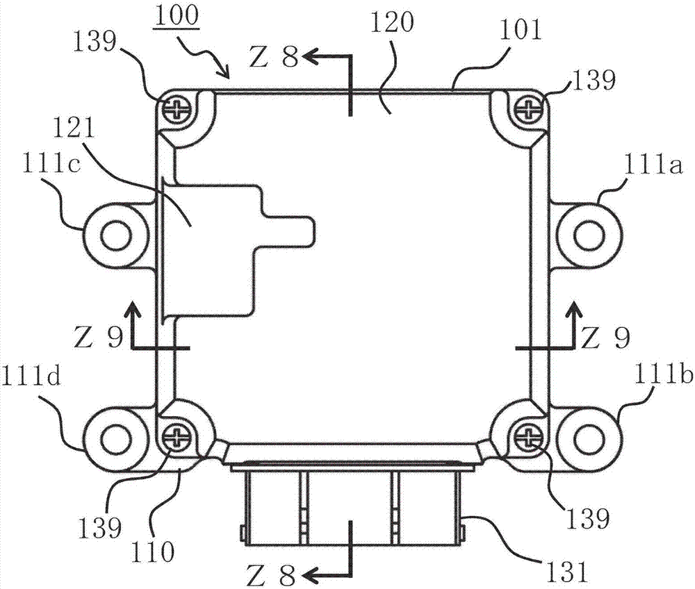
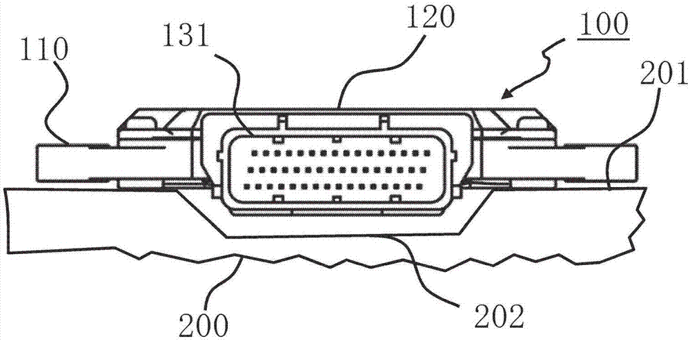
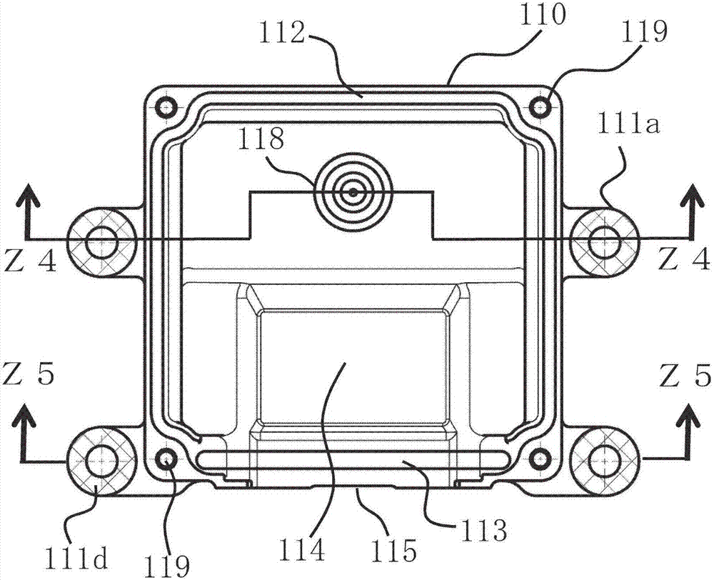
[0040]Next, a top appearance view of a waterproof electronic equipment unit according to an embodiment of the present invention, that is, will be sequentially described. figure 1 ,From figure 1 The appearance of the end face viewed from the mounting side of the middle connection shell is figure 2 , figure 1 The internal top view of the base is image 3 , image 3 The sectional view at the Z4-Z4 line is Figure 4 , image 3 The sectional view at the Z5-Z5 line is Figure 5 , figure 1 The internal top view of the middle cover is Figure 6 , Figure 6 The sectional view at the Z7-Z7 line is Figure 7 Be explained.

[0041] First, in the external view of the unit viz. figure 1 , figure 2 Among them, the waterproof electronic equipment unit 100 (hereinafter sometimes simply referred to as the unit) consists of a housing 101 and a circuit board 130 housed in the housing (refer to Figure 8 ), the casing 101 is comp...


PUM


Abstract

A waterproof electronic equipment unit attached and fixed to a mounted surface having a flat mounting portion and depressed portion is reduced in size by effectively utilizing the depressed portion. A circuit substrate on which is mounted a connector housing is hermetically housed in a frame configured of a base and cover, the base includes a multiple of mounting legs fixed by screwing to a flat mounting portion, a base depressed portion disposed in a mounting surface depressed portion, and an inlet of a water-repellent filter opposing the flat mounting portion across a gap D1, and the connector housing and a high component are disposed in the base depressed portion.

Description

technical field [0001] The present invention relates to a waterproof electronic equipment unit suitable for being directly installed in, for example, a gearbox of an automobile transmission, and more particularly, to a waterproof electronic equipment unit improved so that the provided installation environment can be effectively utilized. Background technique [0002] In a waterproof electronic equipment unit, a circuit board is airtightly accommodated in a frame composed of a base and a cover plate, and a circuit component including a heating element is mounted on the circuit board, and an external wiring part exposed from the case. The connection shell of the base, the cover plate and the joint surface of the connection shell are provided with a waterproof sealing material. In this waterproof electronic equipment unit, the connection shell as a high component usually has two configuration methods. One is to configure it in between the circuit substrate and the cover plate, ...

Claims


Application Information

Patent Timeline
IPC IPC(8): H05K5/06
CPCH05K5/068H05K5/069H05K5/0073H05K5/0082H01R12/724H05K5/0052H05K7/20436
Inventor 桥本光司松本修一
Owner MITSUBISHI ELECTRIC CORP
Why Eureka
Try Eureka