
A thermal environment design method for hypersonic aircraft control rudder gap

A technology for aircraft and control rudders, applied in the field of aircraft, can solve problems such as complex flow, unpredictable, severe thermal environment, etc., and achieve the effect of both engineering and theory, and high data reliability

Active Publication Date: 2020-09-18
BEIJING LINJIN SPACE AIRCRAFT SYST ENG INST +1
View PDF3 Cites 0 Cited by
  • Summary
  • Abstract
  • Description
  • Claims
  • Application Information

AI Technical Summary

Problems solved by technology

[0006] The technical problem of the present invention is to overcome the deficiencies of the prior art, provide a thermal environment design method for the control rudder gap of a hypersonic vehicle, and solve the complex and difficult-to-predict flow state of the control rudder gap area under the ballistic condition of a hypersonic gliding vehicle. Moreover, the severe thermal environment makes it difficult to assess the local heat protection risk, which can effectively reduce the uncertainty of heat protection design and avoid the risk of heat protection design in local areas of the aircraft

Method used


Image

  • A thermal environment design method for hypersonic aircraft control rudder gap
  • A thermal environment design method for hypersonic aircraft control rudder gap
  • A thermal environment design method for hypersonic aircraft control rudder gap

Examples


Embodiment Construction

[0051] In order to make the purpose, technical solution and advantages of the present invention clearer, the following will further describe the public implementation manners of the present invention in detail with reference to the accompanying drawings.

[0052] After several decades of development, the design technology of aircraft aerodynamic thermal environment has also made great progress. It not only has good prediction accuracy for simple flat plates, cones, and leading edge shapes, but also can pass numerical values ​​for aircraft with wings and rudders. The method obtains higher prediction accuracy for the design of aircraft aerodynamic thermal environment. For the solution of the three-dimensional surface heat flow of aircraft with wings and rudders, it is usually obtained by numerically solving the N-S (Navier-Stokes) equation. The numerical method discretizes the space item and the time item, and then iteratively solves the heat flow on the surface of the object. ...


PUM


Abstract

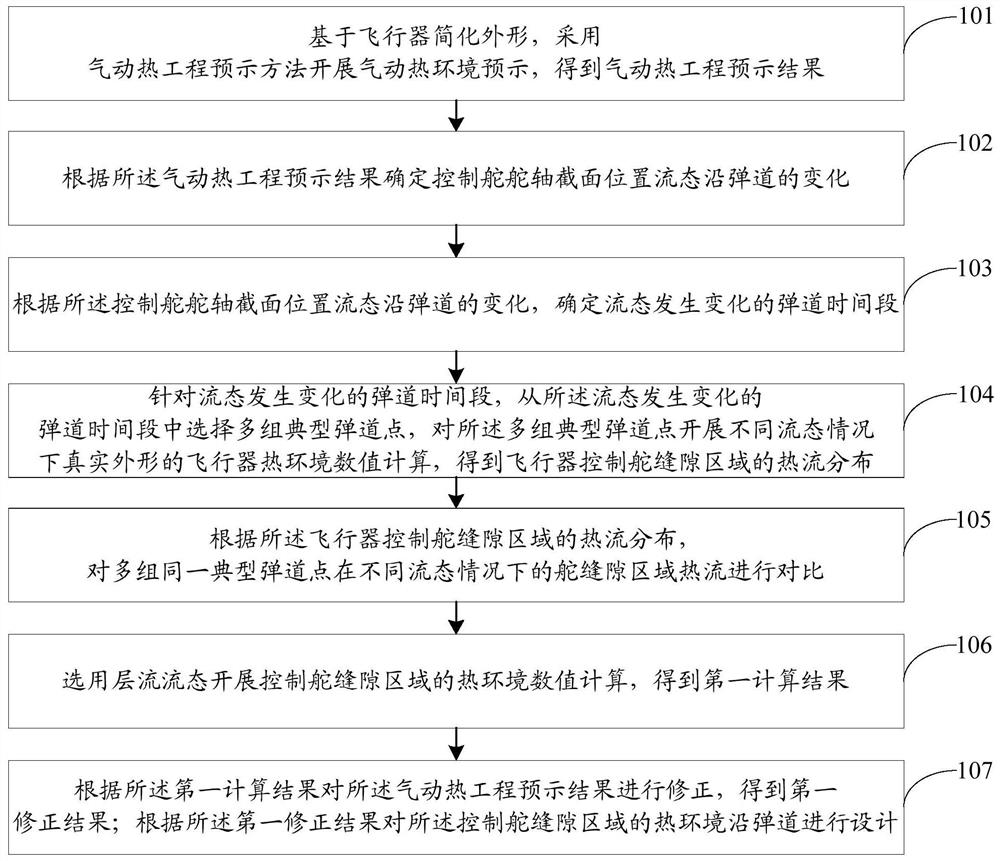
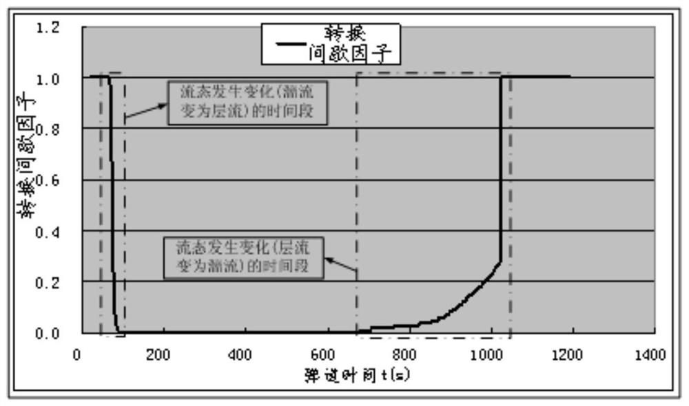
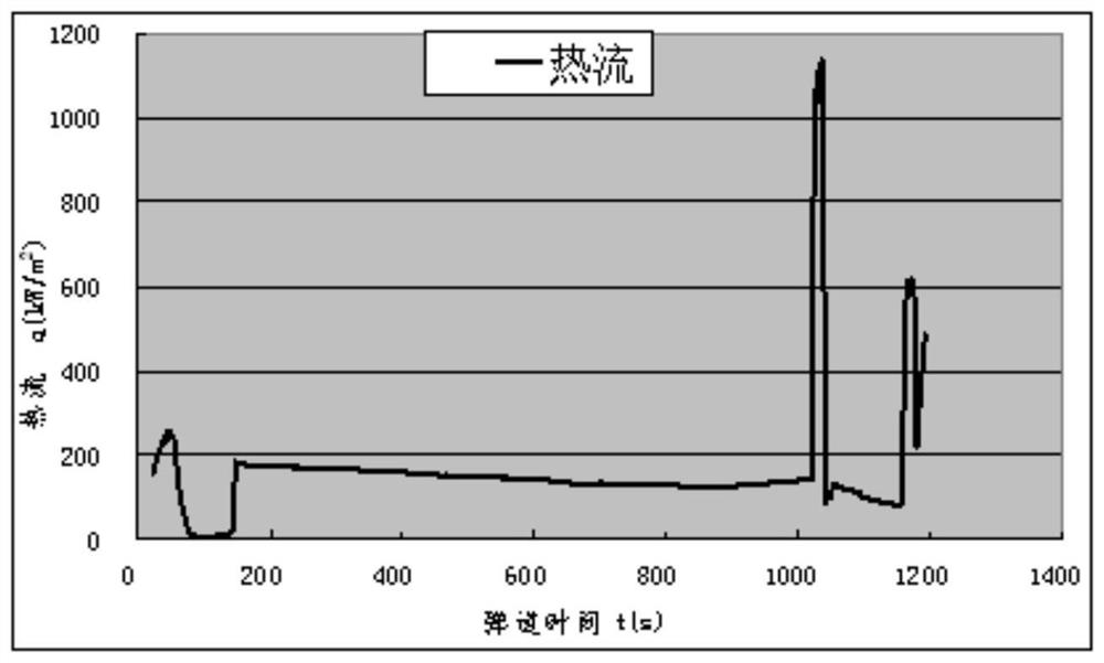
The invention discloses a thermal environment design method of space between control rudders of a hypersonic flight vehicle. The method comprises the steps of on account of a simplified appearance of the hypersonic flight vehicle, adopting a prediction method of aerodynamic heat engineering to conduct a prediction for aerodynamic-heat thermal environment and obtain a prediction result of aerodynamic heat engineering; according to the prediction result of aerodynamic heat engineering, confirming flow pattern changes of a rudder shaft section of a control rudder along a trajectory, and conducting numerical calculation of thermal environment of the flight vehicle on multiple groups of typical trajectories under a condition of different flow patterns according to the trajectory time period of flow pattern changes, then obtaining heat flow distribution of the space between the control rudders of the flight vehicle; choosing a laminar flow state to conduct numerical calculation of thermal environment of the space between the control rudders, and modifying the prediction result of aerodynamic heat engineering according to the calculation result; designing the thermal environment of the space between the control rudders along a trajectory according to the modified result. The thermal environment design method of space between control rudders of a hypersonic flight vehicle resolves the problems that the flow patterns of space between control rudders of a hypersonic gliding flight vehicle are too complex to predict under a ballistic condition, and the thermal environment is so tough that a part of heat-proofing risks are hard to be estimated.

Description

technical field [0001] The invention belongs to the technical field of aircraft, and in particular relates to a thermal environment design method for control rudder gaps of a hypersonic aircraft. Background technique [0002] The hypersonic gliding maneuvering vehicle produces severe friction with the surrounding atmosphere during flight, and the vehicle faces a severe aerodynamic heating environment; for the control rudder area, due to the existence of local complexities such as the gap between the rudder and the cabin, the rudder shaft / cabin rotation gap, and the rudder shaft structure and needs to swing back and forth to adjust the attitude of the aircraft, the thermal environment of the control rudder and the surrounding area is harsh and the distribution is very complicated, especially the thermal environment of the air rudder gap area (the rudder shaft, the cabin near the rudder shaft, and the rudder gap entrance, etc.) is severe and Difficult to predict. [0003] Usu...

Claims


Application Information

Patent Timeline
Patent Type & Authority Patents(China)
IPC IPC(8): G06F30/15G06F119/08
CPCG06F30/15G06F2119/08Y02T90/00
Inventor 聂亮李宇黄建栋于明星聂春生檀妹静王振峰闵昌万王毓栋朱广生
Owner BEIJING LINJIN SPACE AIRCRAFT SYST ENG INST
Learn More