Supercharge Your Innovation With Domain-Expert AI Agents!

vacuum cleaner robot

A technology of vacuum cleaners and robots, which is applied in the direction of robot cleaning machines, cleaning equipment, cleaning devices, etc., can solve the problems of low power of motor fan unit, small dust absorption capacity, etc., and achieve the effect of high volume flow

Active Publication Date: 2019-10-18
EUROLIFTERS HLDG NV
View PDF19 Cites 0 Cited by
  • Summary
  • Abstract
  • Description
  • Claims
  • Application Information

AI Technical Summary

Problems solved by technology

[0006] A disadvantage of these known vacuum cleaner robots is that they have only a small dust absorption capacity
This is due to the fact that the dust intake is only achieved by the brushing action of the rotating brush roller, or that the motor fan unit used has a very low power

Method used


Image

  • vacuum cleaner robot
  • vacuum cleaner robot
  • vacuum cleaner robot

Examples


Embodiment Construction

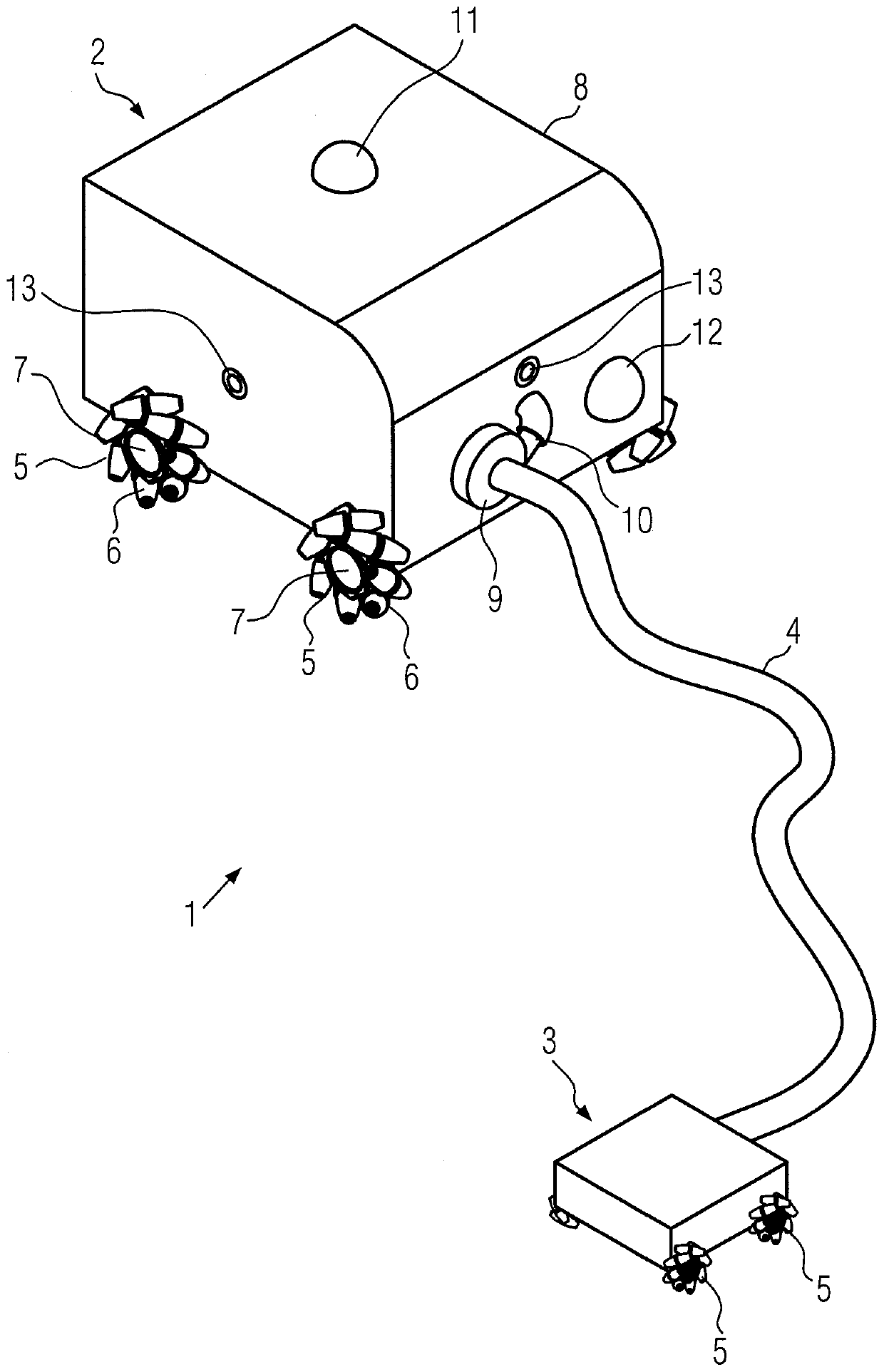
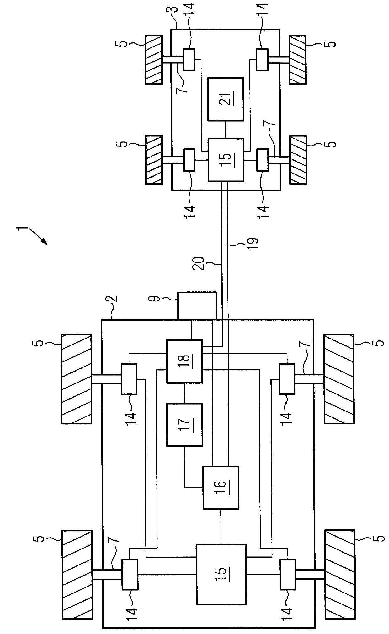
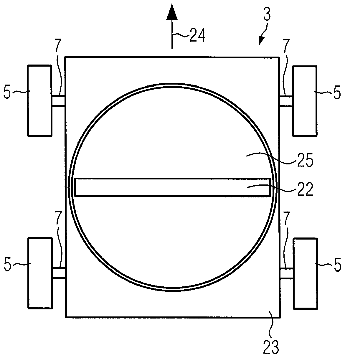
[0089] figure 1 A schematic diagram of a first embodiment of a vacuum cleaner robot 1 is shown. The shown vacuum cleaner robot 1 comprises a dust collection unit 2 and a floor nozzle 3 connected to the dust collection unit 2 via a flexible suction hose 4 . The vacuum cleaner robot 1 thus has a two-part design, i.e. the dust collection unit 2 and the floor nozzle 3 define a single unit, the dust collection unit 2 and the floor nozzle 3 being connected to each other only by means of the suction hose 4 .

[0090] The dust collection unit 2 is supported on four wheels 5, all of which are configured as omnidirectional wheels. Each omni wheel 5 has a plurality of rotatably mounted rollers 6 provided on its circumference. The axes of rotation of said rollers 6 are all non-parallel to the wheel axis 7 of the corresponding omni wheel. For example, the axes of rotation of the rollers may be at an angle of 45° relative to the respective wheel axes. The surface of the roll or roll bo...


PUM


Abstract

The invention relates to a vacuum cleaner robot (1) comprising a dust collection unit (2) and a floor nozzle (3) supported on wheels (5), said floor nozzle comprising drive means (14, 15), The drive means (14, 15) are used to drive at least one of the wheels of the ground nozzle. One, more or all of the wheels of the ground nozzle are omni-directional wheels. The floor nozzle includes a base plate having a base surface that faces a surface to be cleaned when the vacuum cleaner robot is in operation. An air channel is arranged in the base plate, the air channel is parallel to the base surface, and the air to be cleaned enters the ground nozzle through the air channel. The ground nozzle includes a rotating member for rotating the air flow channel about an axis perpendicular to the base surface.

Description

technical field [0001] The present invention relates to vacuum cleaner robots. Background technique [0002] Conventional vacuum cleaners are operated by a user who moves the vacuum cleaner across the surface to be cleaned, in particular the floor nozzle which draws in dust. Conventional canister vacuum cleaners, for example, include a housing mounted to rollers and / or slides. A dust collection container is arranged in the casing, and a filter bag is arranged in the dust collection container. The floor nozzle is connected to the dust chamber via a suction pipe and a suction hose. In conventional canister vacuum cleaners, the housing is additionally equipped with a motor-fan unit which generates a negative pressure in the dust container. Therefore, the motor fan unit is arranged downstream of the floor nozzle, the suction pipe, the suction hose as well as the dust collection container and the filter bag when viewed in the air flow direction. Since the air flowing through ...

Claims


Application Information

Patent Timeline
Patent Type & Authority Patents(China)
IPC IPC(8): A47L5/22A47L9/02A47L9/04A47L9/28
CPCA47L5/22A47L9/02A47L9/0477A47L9/28A47L9/2821A47L9/2868A47L2201/00G05D1/0248A47L5/362A47L9/066B60B19/003A47L9/009A47L9/04G05D1/024G05D1/0246G05D1/0255G05D1/0257G05D1/0295
Inventor 拉尔夫·赛耶简·舒尔廷克
Owner EUROLIFTERS HLDG NV
Features
  • R&D
  • Intellectual Property
  • Life Sciences
  • Materials
  • Tech Scout
  • Unparalleled Data Quality
  • Higher Quality Content
  • 60% Fewer Hallucinations
Learn More