Bridge equipment

A kind of equipment and bridge technology, applied in the field of bridge equipment, can solve the problems of low work efficiency, increased cost, inconvenient use, etc., and achieve the effect of improving the stability of forward and backward movement

Inactive Publication Date: 2017-10-13
俞岳田
View PDF4 Cites 5 Cited by
  • Summary
  • Abstract
  • Description
  • Claims
  • Application Information

AI Technical Summary

Problems solved by technology

[0002] In the process of bridge construction, a lot of ropes need to be used. After the ropes are used, the ropes need to be wound up, so as to facilitate storage, handling, carrying, etc. The existing rope winding devices are often only a single winding rope, and the work efficiency is relatively high. Low, you need to replace the rope drum after winding one, and then continue to wind the rope, which is a waste of man-hours and low in efficiency. In addition, if you want to install more rope winding devices, you need to set up additional driving devices, which increases the cost and is extremely difficult to use. the inconvenience

Method used


Image

  • Bridge equipment
  • Bridge equipment
  • Bridge equipment

Examples


Embodiment Construction

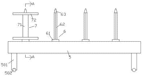
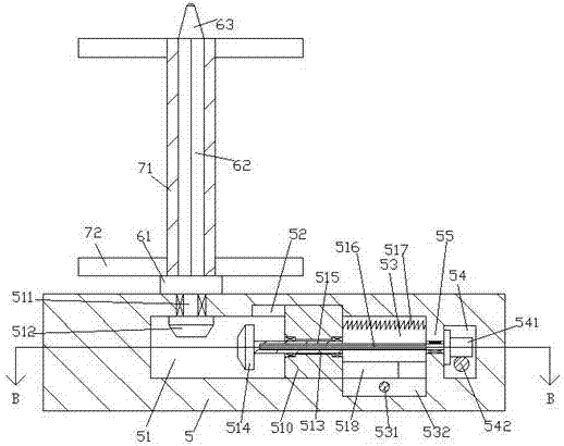
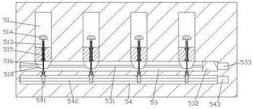
[0021] Such as Figure 1-Figure 6 As shown, a bridge device of the present invention includes a base frame 5 and rope winding assemblies 6 evenly distributed on the top end surface of the base frame 5, and a vertical arm 501 is fixedly installed on the bottom of the base frame 5, and the vertical arm 501 Universal wheels 502 are rotatably installed at the bottom, so as to facilitate the movement of the base frame 5. The base frame 5 below each of the rope-wrapping components 6 is provided with a drive cavity 51 extending to the front side. The rear side of the driving cavity 51 is communicated with a first hollow cavity 53 extending left and right, and a second hollow cavity 54 is provided in the base frame 5 on the front side of the first hollow cavity 53. The first hollow cavity 53 is connected to A partition plate 55 is provided between the second hollow chambers 54, and a guide groove 52 is provided on the inner top of the front side of each first hollow chamber 53, and ea...


PUM


Abstract

The invention discloses bridge equipment. The bridge equipment comprises a bed frame and rope winding assemblies evenly distributed on the end face of the top of the bed frame. Stand arms are fixedly mounted at the bottom of the bed frame. Rotatable universal wheels are mounted at the bottoms of the stand arms. A driving cavity extending forwards is formed in the position, below the corresponding rope winding assembly, in the bed frame. The rear side of each driving cavity is provided with a first hollow cavity extending left and right in a communicating mode. A second hollow cavity is formed in the position, in front of the corresponding first hollow cavity, in the bed frame. A partition plate is arranged between each first hollow cavity and the corresponding second hollow cavity. A movement guiding groove is formed in the position, in front of the corresponding first hollow cavity, of the inner top of the bed frame. A first sliding frame extending downwards is arranged in each movement guiding groove. The bridge equipment is simple in structure, mounting of a plurality of rope winding drums can be achieved, an operator does not need to replace the rope winding drums when a rope is wound on one of the rope winding drums, time and effort are saved, and the efficiency is improved; and in addition, a driving device does not need to be additionally arranged, the manufacturing cost is lowered, and the enterprise purchase cost is lowered.

Description

technical field [0001] The invention relates to the field of bridges, in particular to bridge equipment. Background technique [0002] In the process of bridge construction, a lot of ropes need to be used. After the ropes are used, the ropes need to be wound up, so as to facilitate storage, handling, carrying, etc. The existing rope winding devices are often only a single winding rope, and the work efficiency is relatively high. Low, you need to replace the rope drum after winding one, and then continue to wind the rope, which is a waste of man-hours and low in efficiency. In addition, if you want to install more rope winding devices, you need to set up additional driving devices, which increases the cost and is extremely difficult to use. the inconvenience. Contents of the invention [0003] The technical problem to be solved by the present invention is to provide a bridge device, which can solve the above-mentioned problems in the prior art. [0004] The present invent...

Claims


Application Information

Patent Timeline
Patent Type & Authority Applications(China)
IPC IPC(8): B65H54/20B65H54/74
CPCB65H54/20B65H54/74B65H2403/43B65H2403/46B65H2403/52B65H2403/55B65H2403/90B65H2701/35
Inventor 俞岳田
Owner 俞岳田
Why Eureka
Try Eureka