microwave cooking device
A cooking device and microwave technology, which is applied to microwave heating, electric heating devices, household stoves/stoves, etc., can solve the problem of inability to detect microwave leakage of microwave shielding layer microwave cooking devices, and achieve the effect of accurate monitoring and risk reduction.
- Summary
- Abstract
- Description
- Claims
- Application Information
AI Technical Summary
Problems solved by technology
Method used
Image
Examples
Embodiment 1
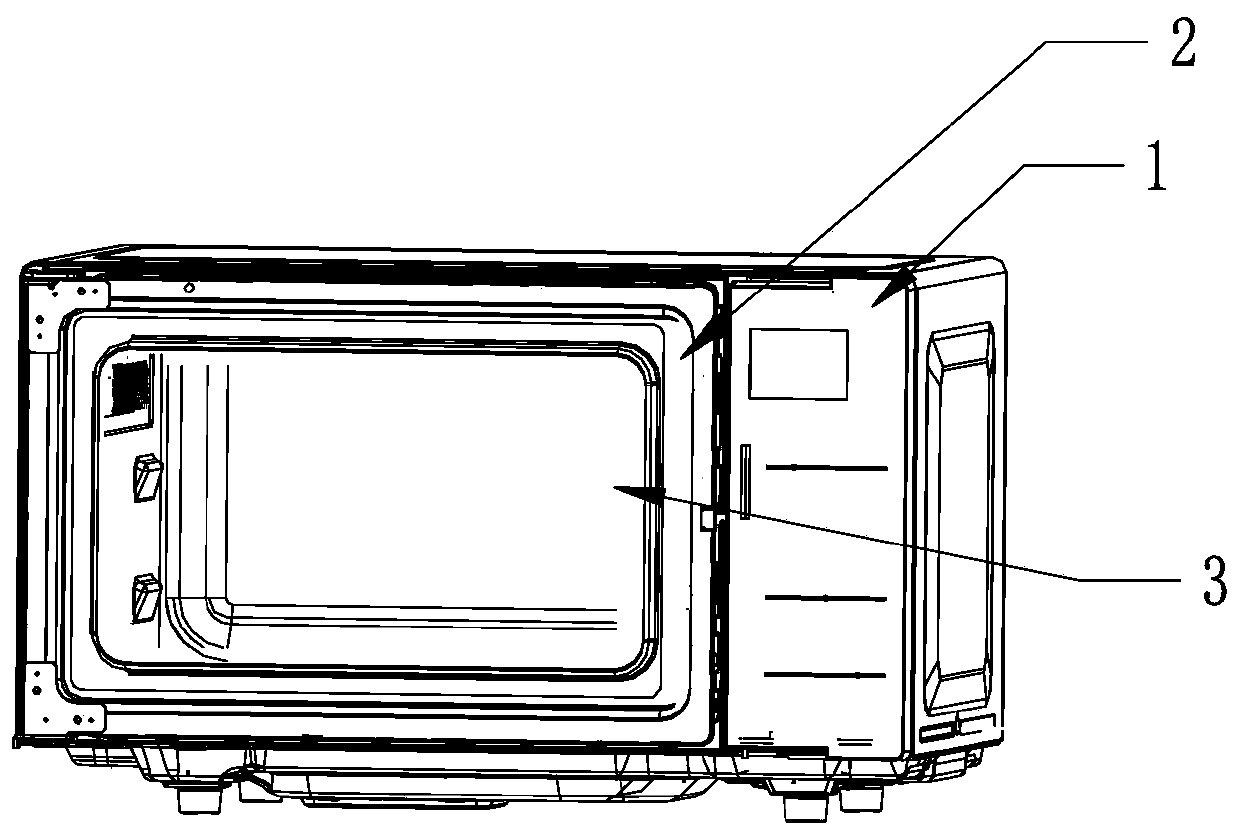
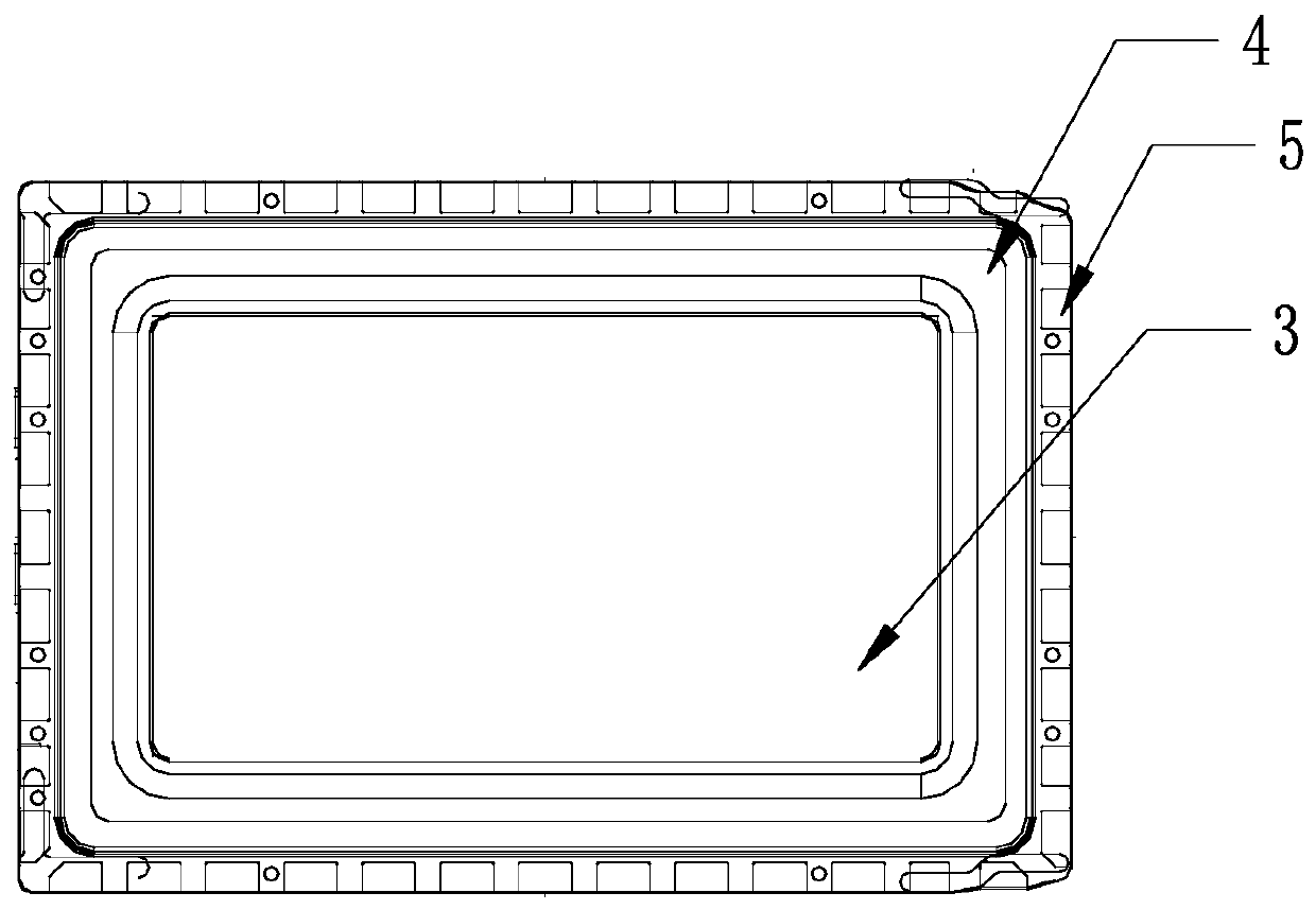
[0035] See figure 1 , the microwave cooking device of the first embodiment includes a furnace body 1 and a furnace door 2 . Wherein, the structure of furnace door 2 can refer to figure 2 and image 3 .
[0036] It should be noted that the first embodiment only takes the visible furnace door 2 as an example for illustration. Therefore, the microwave shielding layer 12 of the oven door 2 adopts visible materials. In addition, a visible observation window 3 is formed on the furnace door 2 .
[0037] Without loss of generality, the oven door 2 in the microwave cooking device of the first embodiment may also be invisible. That is, the electromagnetic radiation detection assembly mentioned below can also be installed on the side of the conventional microwave shielding layer 12 away from the furnace body 1 .
[0038] Specifically, the furnace door 2 of the first embodiment includes a microwave shielding layer 12 and an electromagnetic radiation detection component, the electro...
Embodiment 2
[0065] See Figure 8 , and Embodiment 1 is different in that the microwave cooking device of Embodiment 2 has a loop antenna 14 as its probe. Assuming that the area surrounded by a loop antenna 14 is A, then the loop antenna 14 can effectively receive the microwave intensity in the area with the current area A.
[0066] Wherein, at least one loop antenna 14 is arranged on one furnace door 2 . When one loop antenna 14 cannot effectively cover the entire surface area of the furnace door 2, multiple loop antennas 14 can be arranged in an array. The number of specific loop antennas 14 can be set according to the detection accuracy, and the microwave receiving range of the loop antennas 14 should cover the surface of the furnace door 2 as much as possible to ensure the effectiveness of detection. When the number of loop antennas 14 is multiple, the loop antennas 14 in the adjacent detection probe 7 are closely adjacent to each other, so as to ensure the effectiveness of detecti...
PUM
 Abstract
Description
Claims
Application Information
 - R&D
- Intellectual Property
- Life Sciences
- Materials
- Tech Scout
- Unparalleled Data Quality
- Higher Quality Content
- 60% Fewer Hallucinations
Browse by: Latest US Patents, China's latest patents, Technical Efficacy Thesaurus, Application Domain, Technology Topic, Popular Technical Reports.
© 2025 PatSnap. All rights reserved.Legal|Privacy policy|Modern Slavery Act Transparency Statement|Sitemap|About US| Contact US: help@patsnap.com


