Angular rate calculation and compensation method for table drift caused by base motion

A compensation method and angular rate technology, applied in the field of three-axis inertial platform system, can solve the problems of losing the control function of the outer frame axis, no clear calculation method, and difficulty in meeting the requirements of large maneuvering motion of the carrier, so as to improve navigation and guidance The effect of precision

Active Publication Date: 2017-10-24
BEIJING INST OF AEROSPACE CONTROL DEVICES
View PDF6 Cites 7 Cited by
  • Summary
  • Abstract
  • Description
  • Claims
  • Application Information

AI Technical Summary

Problems solved by technology

[0003] Due to the phenomenon of "frame locking" in the three-axis inertial platform system, that is, the inner frame and the outer frame are in the same plane. The platform system loses one degree of freedom; on the other hand, because the gyroscope originally used to control the axis of the outer frame cannot feel the rotation of the axis of the outer frame, the control of the axis of the outer frame is lost
[0004] At present, the existing measures can only meet the motion requirements of the three-axis inertial platform system on the carrier with limited maneuvering attitude, and it is difficult to meet the requirements of the large maneuvering motion of the carrier
In addition, even if the angle of the inner frame works at a small angle, the movement of the base will cause the drift of the table body. The magnitude of the drift angular rate is only a qualitative analysis at present, and there is no clear calculation method yet

Method used


Image

  • Angular rate calculation and compensation method for table drift caused by base motion
  • Angular rate calculation and compensation method for table drift caused by base motion
  • Angular rate calculation and compensation method for table drift caused by base motion

Examples


Embodiment Construction

[0028] In order to make the purpose, technical solution and advantages of the present invention clearer, the following will further describe the public implementation manners of the present invention in detail with reference to the accompanying drawings.

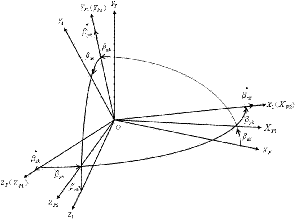
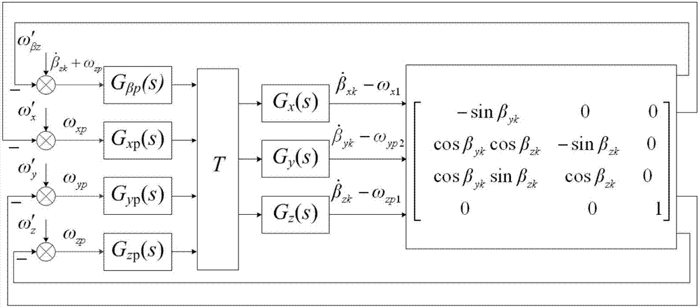
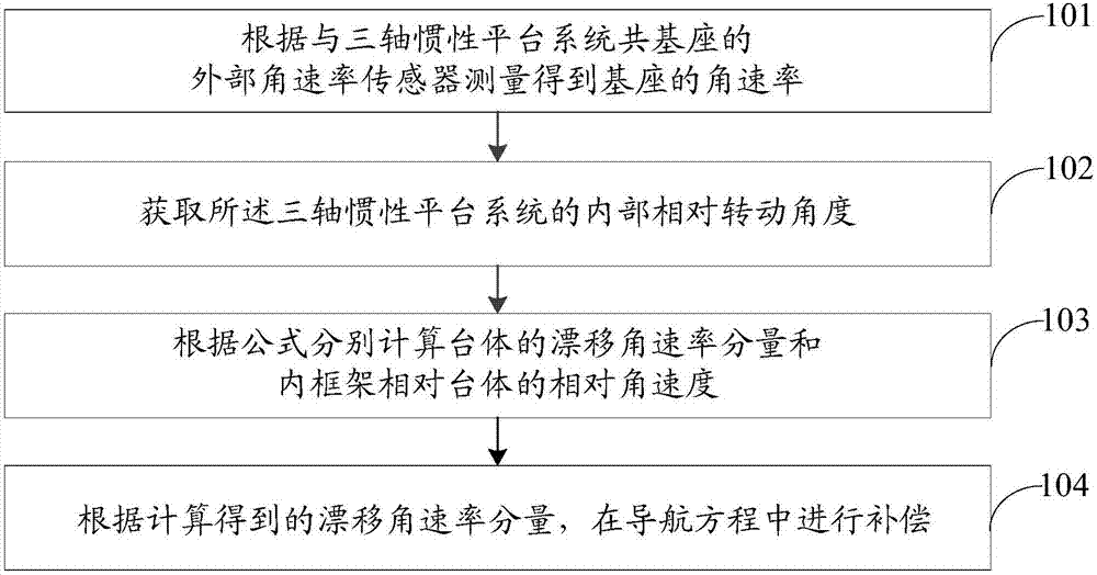
[0029] The method for calculating and compensating the angular rate of the platform body drift caused by the movement of the base in the present invention is aimed at the plane coordinate resolver, and the angular rate ω of the base movement is used x1 , ω y1 and ω z1 , the inner frame around the body coordinate system Z P Angle of shaft rotation β zk , Y of the outer frame around the body coordinate system of the inner frame P1 Angle of shaft rotation β yk , and the X of the base around the body coordinate system of the outer frame P2 Angle of shaft rotation β xk 6 variables are used as input information, and the drift angular rate ω of the platform is calculated after information fusion xp , ω yp and ω zp ; and ac...


PUM


Abstract

The invention discloses an angular rate calculation and compensation method for table drift caused by a base motion. The method is applied to a three-axis inertial platform system, and comprises the following steps: measuring to obtain a Y1-axis angular rate omega y1 and a Z1-axis angular rate omega z1 of the base according to an external angular rate sensor on the base on which the three-axis inertial platform system is arranged; acquiring an internal relative rotation angle of the three-axis inertial platform system; and resolving according to the measured angular rate of the base and the internal relative rotation angle so as to obtain a drifting angular rate component, and compensating in a navigation equation. According to the method disclosed by the invention, the production mechanism of the table drift caused by the base motion in the three-axis inertial platform system is analyzed, so that the drifting angular rate is calculated to be used for compensation, and the navigation and guidance accuracy is improved.

Description

technical field [0001] The invention belongs to the technical field of three-axis inertial platform systems, and in particular relates to an angular rate calculation and compensation method for platform body drift caused by base movement. Background technique [0002] Three-axis inertial platform systems have been widely used on vehicles with limited maneuvering attitudes, that is, in vehicles that do not simultaneously exhibit large attitude angles around two axes during flight. However, sometimes the carrier rockets and ballistic missiles need to maneuver and change orbits, especially tactical missiles, satellites and many military aircraft need to work in full attitude and large maneuvering state. Under such conditions, the platform of the three-axis inertial platform system is required body remains stable. [0003] Due to the phenomenon of "frame locking" in the three-axis inertial platform system, that is, the inner frame and the outer frame are in the same plane. The...

Claims


Application Information

Patent Timeline
Patent Type & Authority Applications(China)
IPC IPC(8): G01C25/00
CPCG01C25/005
Inventor 魏宗康何远清
Owner BEIJING INST OF AEROSPACE CONTROL DEVICES
Why Eureka
Try Eureka