

Refrigerator
A technology for refrigerators and storage rooms, which is applied in the field of refrigerators and can solve the problems that users cannot recognize the functions of sterilization and deodorization
- Summary
- Abstract
- Description
- Claims
- Application Information
AI Technical Summary
Problems solved by technology
Method used
Image

Examples
Embodiment Construction
[0036] Hereinafter, modes for implementing the present invention (hereinafter referred to as embodiments) will be described using the drawings.
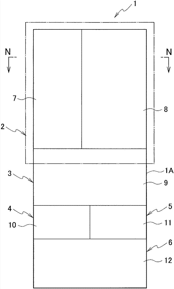
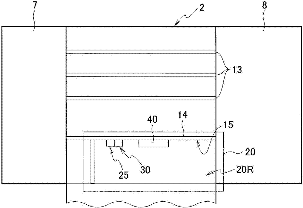
[0037] figure 1 It is a front view which shows the whole of the refrigerator which concerns on embodiment of this invention. figure 2 is to show the figure 1 It is a front view of a state in which the left door 7 and the right door 8 of the refrigerating compartment 2 of the refrigerator 1 are opened.
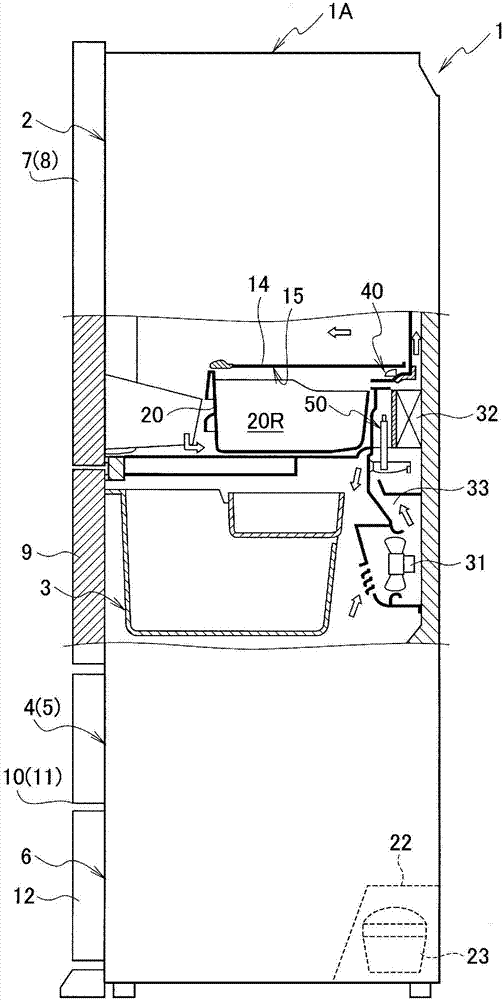
[0038] figure 1 and figure 2 The illustrated refrigerator 1 has a main body 1A. The main body 1A of the refrigerator 1 has an outer box made of outer side panels and an inner box made of inner side panels, and a heat-insulating box is arranged between the outer box and the inner box.
[0039] like figure 1 As shown, in the main body 1A, a refrigerating compartment 2 and a vegetable compartment 3 are arranged sequentially from the upper side, and an ice-making compartment 4 and an upper freezer compartment are arranged side by ...
PUM
 Abstract
Description
Claims
Application Information