Powder detection device and toner replenishment device
A technology for detecting devices and toners, which can be used in instruments, equipment for electric recording technology using charge patterns, optics, etc., and can solve problems such as false detection
- Summary
- Abstract
- Description
- Claims
- Application Information
AI Technical Summary
Problems solved by technology
Method used
Image

Examples
no. 1 approach
[0021] The powder detection device of the present invention is embodied, for example, as a toner detection device for detecting toner used in electrophotographic image forming processing. The toner detection device of the first embodiment of the present invention is applied to the image forming apparatus 1 .
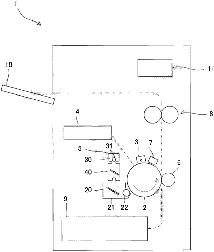
[0022] like figure 1 As shown, the image forming apparatus 1 includes: a photoreceptor drum 2, a charging device 3, an exposure device 4, a developing device 5, a transfer device 6, a cleaning unit 7, a fixing device 8, a paper feed tray 9, a paper discharge tray 10, and a control unit. Section 11.
[0023] The photosensitive drum 2 is an example of an electrostatic latent image carrier, has a photosensitive layer on its peripheral surface, and rotates in one direction. The charging device 3 charges the peripheral surface of the photoreceptor drum 2 to a predetermined potential. The exposure device 4 forms an electrostatic latent image by exposing the peripheral surfa...
no. 2 approach
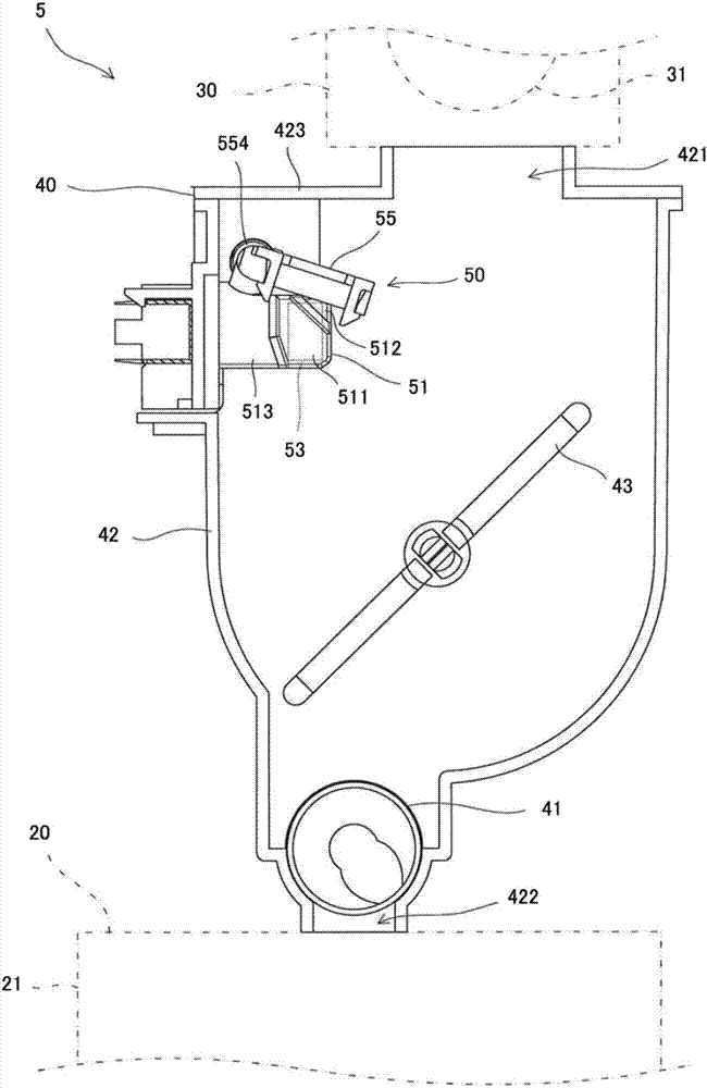
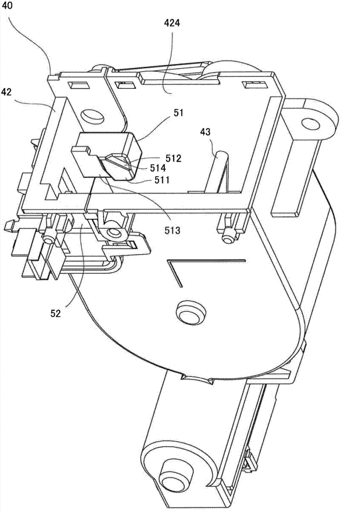
[0058] When the presence or absence of toner is detected by the optical sensors 53 and 54, it is preferable to perform the following process. In the process of supplying toner from the toner cartridge 30 to the hopper 40 and in the process of replenishing the toner from the hopper 40 to the developing tank 21, the presence or absence of toner at a predetermined height in the hopper container 42 is repeated. determination. Then, the cleaning member 55 and the agitating member 43 are rotated next while the toner is being supplied from the toner cartridge 30 to the hopper 40 and while the toner is being replenished from the hopper 40 to the developing tank 21 .
[0059] like Figure 9 As shown, the control unit 11 first resets the sampling frequency SC of the output value of the optical sensor 54 (S1). Moreover, the control part 11 also resets the light-shielding counter IC which is the number of times of sampling the output value which shows the light-shielding state of the op...
no. 3 approach
[0072] Such as Figure 10 as well as Figure 11 As shown, the operation of supplying the toner from the toner cartridge 30 to the hopper 40 is preferably performed as follows. That is, when the control unit 11 stops the cleaning member 55, it is preferable to stop the cleaning member 55 after a predetermined period of time has elapsed from the time when the light path from the optical sensors 53 and 54 is blocked. The timing at which the transmission period of the optical path to the optical sensors 53 and 54 has changed. Specifically, processing is performed as follows.
[0073] When the control unit 11 determines that the toner is not accommodated up to a predetermined height in the hopper container 42, it requests to start replenishing the toner from the toner cartridge 30 to the hopper 40 (S21), and starts to drive the cleaning member 55 to rotate. The motor 556 of the hopper 40 and the motor which rotates the supply roller 31 (S22). Accordingly, an amount of toner cor...
PUM
 Abstract
Description
Claims
Application Information
 - R&D
- Intellectual Property
- Life Sciences
- Materials
- Tech Scout
- Unparalleled Data Quality
- Higher Quality Content
- 60% Fewer Hallucinations
Browse by: Latest US Patents, China's latest patents, Technical Efficacy Thesaurus, Application Domain, Technology Topic, Popular Technical Reports.
© 2025 PatSnap. All rights reserved.Legal|Privacy policy|Modern Slavery Act Transparency Statement|Sitemap|About US| Contact US: help@patsnap.com