Portable cutting device

A cutting device and convenient technology, applied in the direction of coupling device, connecting device parts, electrical components, etc., can solve the problems of cable self-heavy, loose plugging, poor contact, etc., to improve plugging stability, prevent The effect of loose plugging

Inactive Publication Date: 2017-11-03
邵潘英
View PDF1 Cites 14 Cited by
  • Summary
  • Abstract
  • Description
  • Claims
  • Application Information

AI Technical Summary

Problems solved by technology

[0002] At present, cutting machines are widely used, and the motor drives the cutting gear to rotate at high speed to achieve the purpose of cutting mainly through plugging in power supply. Due to external factors such as pulling, the plugging is loose and leads to poor contact. The existing cutting machines are powered by manual plugging. Due to the instability of manual plugging, arcs are likely to be generated during the plugging process and cause the risk of electric shock. , there are great disadvantages, and at the same time, there is a certain degree of danger in the cutting operation process, and an emergency power-off device should be installed to enhance the protection during cutting operations

Method used


Image

  • Portable cutting device
  • Portable cutting device
  • Portable cutting device

Examples


Embodiment Construction

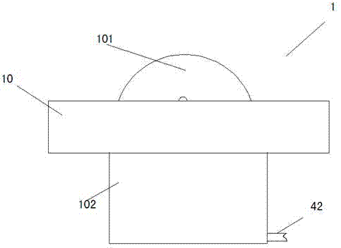
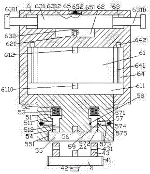
[0024] Such as Figure 1-Figure 8 As shown, a convenient cutting device of the present invention includes a cutting machine 1 and a socket 6. The cutting machine 1 is composed of a cutting table 10, a cutting gear 101 embedded in the cutting table 10 and connected in rotation, and arranged on a The base 102 at the bottom of the cutting table 10 is composed of a pin head 4 provided at the bottom of the socket 6, and a power cord 42 connected to the bottom surface of the rear side of the base 102 is provided at the bottom of the socket 6, and the power cord 42 is used for For the power supply transmission of the cutting machine 1, the inner bottom of the socket 6 is provided with a container 61, and the left and right sides of the container 61 are provided with chute 64, and the chute 64 is provided with a stud 641, The top of the stud 641 is connected to the motor 642, and the housing 61 is provided with a lifting plate 611, and both ends of the lifting plate 611 penetrate into...


PUM


Abstract

The invention discloses a portable cutting device. The portable cutting device comprises a cutting machine and a socket, wherein the cutting machine comprises a cutting table, a cutting gear and a base, the cutting gear is embedded into the cutting table and is connected with the cutting table in a rotating and matching way, the base is arranged at a bottom part of the cutting table, a pin is arranged at a bottom part of the socket, a power line is arranged at a bottom part of the pin and is connected with a bottom surface of a rear side of the base, an accommodating bin is arranged at a bottom part of the socket, sliding grooves are formed in a left side and a right side of the accommodating bin, studs are arranged in the sliding grooves, top parts of the studs are connected with a motor, a lifting plate is arranged in the accommodating bin, two side ends of the lifting plate penetrate through the sliding grooves and are in threaded connection with the studs in a matching way, a lifting block is arranged at a bottom part of the lifting plate, the bottom part of the lifting block penetrates through a bottom wall of the socket and is movably connected with the bottom wall of the socket in a matching way, first sliding grooves are symmetrically formed in a left part and a right part of the lifting block, hole grooves are formed in top parts of the first sliding grooves, and a connection groove is formed in an end surface of the bottom part of the lifting block. The portable cutting device is simple in structure and high in safety, and is convenient to operate, and automatic connection power supply can be achieved.

Description

technical field [0001] The invention relates to the technical field of cutting, in particular to a convenient cutting device. Background technique [0002] At present, cutting machines are widely used, and the motor drives the cutting gear to rotate at high speed to achieve the purpose of cutting mainly through plugging in power supply. Due to external factors such as pulling, the plugging is loose and leads to poor contact. The existing cutting machines are powered by manual plugging. Due to the instability of manual plugging, arcs are likely to be generated during the plugging process and cause the risk of electric shock. , There are great disadvantages, and at the same time, there is a certain danger in the cutting operation process, and an emergency power-off device should be installed to enhance the protection during the cutting operation. Contents of the invention [0003] The technical problem to be solved by the present invention is to provide a convenient cutting...

Claims


Application Information

Patent Timeline
Patent Type & Authority Applications(China)
IPC IPC(8): H01R13/627H01R13/631H01R13/66H01R13/707H01R13/502
CPCH01R13/6278H01R13/502H01R13/631H01R13/6633H01R13/6683H01R13/707
Inventor 邵潘英
Owner 邵潘英
Why Eureka
Try Eureka