Electric welding device

A technology of electric welding machine and seat body, which is applied in the direction of welding protection device, arc welding equipment, welding equipment, etc. It can solve problems such as poor contact, loose plug connection, electric shock, etc., so as to improve the stability of plug connection and prevent loose plug connection Effect

Inactive Publication Date: 2018-07-03
童浩
View PDF0 Cites 0 Cited by
  • Summary
  • Abstract
  • Description
  • Claims
  • Application Information

AI Technical Summary

Problems solved by technology

[0002] At present, electric welding machines are used more and more widely, and they rely on plug-in power supply to work normally. Therefore, whether the electric welding machine is plugged in stably and whether the power supply is safe is the basis for determining whether the electric welding machine can work normally. The cables are generally set long and have a large weight, which is easily affected by external factors such as dragging and pulling, which may cause loose connection and poor contact. Electric arc is generated, there is a danger of electric shock, and there are great disadvantages. In order to avoid safety accidents, emergency treatment devices should be added during use to increase the safety of power supply.

Method used


Image

  • Electric welding device
  • Electric welding device
  • Electric welding device

Examples


Embodiment Construction

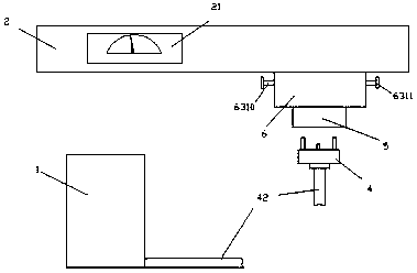
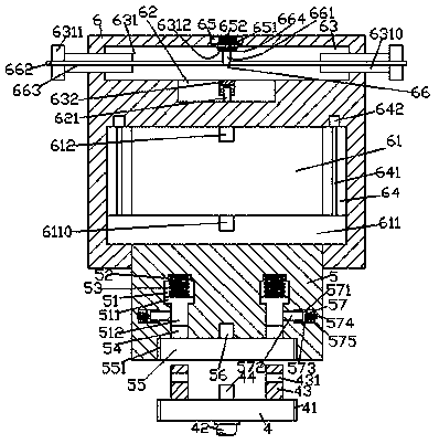
[0024] Such as Figure 1-Figure 8 As shown, an electric welding device of the present invention includes an electric welding machine 1 and a frame body 2, a converter 21 is provided on the left front face of the frame body 2, a seat body 6 is provided on the bottom right side of the frame body 2, and the conversion The device 21 is connected to the base body 6 through a circuit, and the voltage in the base body 6 can be adjusted through the converter 21, so as to meet the electric connection requirements of electric welding machines of different powers. The bottom of the base body 6 is provided with Plug 4, the bottom of the plug 4 is provided with a cable 42 connected to the electric welding machine 1, and the inner bottom of the seat body 6 is provided with a cavity 61, and the left and right sides of the cavity 61 are provided with sliding grooves 64 , the sliding groove 64 is provided with a screw rod 641, the top of the screw rod 641 is connected with the motor 642, the c...


PUM


Abstract

The invention discloses an electric welding device which comprises a welding machine and a frame body; a converter is arranged at the left front end face of the frame body; a base body is arranged atthe bottom of the right side of the frame body; a plug is arranged at the bottom of the base body; a wire cable connected with the welding machine is arranged at the bottom of the plug; a cavity is formed in the bottom of the base body; sliding grooves are formed in the left side and the right side of the cavity; spiral rods are arranged in the sliding grooves; the tops of the spiral rods are connected with motors; a sliding plate is arranged in the cavity; the two side ends of the sliding plate enter into the sliding grooves and are connected with spiral threads of the spiral rods in a fit manner; a fixed connection block is arranged at the bottom of the sliding plate; the bottom of the fixed connection block passes through the end wall of the base body and is connected with the base bodyin a slidingly fit manner; first groove parts are formed in the fixed connection block in a left-and-right corresponding manner; placement grooves are formed in the tops of the first groove parts; aconnecting groove is formed in the bottom end face of the fixed connection block; a penetrable hole is formed in the part, between the connecting groove and each first groove part of the fixed connection block; a second groove part is formed in the outer side wall of each penetrable hole; first sliding blocks are arranged in the first groove parts; a first pressure spring is arranged between the top of each first sliding block and the corresponding placement groove; and sliding rods entering into the penetrable holes are arranged at the bottoms of the first sliding blocks. The electric weldingdevice is reasonable in structure and simple to operate, can be automatically plugged to be electrified and is high in plugging firmness.

Description

technical field [0001] The invention relates to the technical field of welding, in particular to an electric welding device. Background technique [0002] At present, electric welding machines are used more and more widely, and they rely on plug-in power supply to work normally. Therefore, whether the electric welding machine is plugged in stably and whether the power supply is safe is the basis for determining whether the electric welding machine can work normally. The cables are generally set long and have a large weight, which is easily affected by external factors such as dragging and pulling, which may cause loose connection and poor contact. There is a risk of electric shock due to the generation of electric arc, which has great disadvantages. In order to avoid the occurrence of safety accidents, emergency treatment devices should be added during use to increase the safety of power supply. Contents of the invention [0003] The technical problem to be solved by the ...

Claims


Application Information

Patent Timeline
Patent Type & Authority Applications(China)
IPC IPC(8): B23K9/00B23K9/32
CPCB23K9/00B23K9/32B23K9/321
Inventor 童浩
Owner 童浩
Why Eureka
Try Eureka