Spraying equipment for backlight component

A technology of spraying equipment and backlight, applied in the direction of spraying device, liquid spraying device, etc., can solve the problems of increasing the labor load of the staff, easy falling to the outside of the work box, and difficult to clean the inside of the work box, so as to reduce the amount of cleaning and facilitate cleaning effect

Inactive Publication Date: 2017-11-10
YANCHENG SANDING ELECTRONICS TECH CO LTD
View PDF0 Cites 0 Cited by
  • Summary
  • Abstract
  • Description
  • Claims
  • Application Information

AI Technical Summary

Problems solved by technology

[0002] As we all know, the spraying equipment for backlight components is an auxiliary device for spraying paint on its components during the processing of backlights, and it is widely used in the field of production and processing; the existing spraying equipment for backlight components includes The base, working box, motor, connecting pipe, bracket and spray gun, the working box and the bracket are respectively arranged on the left and right sides of the top of the base, a working chamber is arranged in the working box, the motor is arranged on the top of the working box, and the bottom output end of the motor is provided with Rotating shaft, and stirring blades are arranged on the rotating shaft, and the stirring blades are located in the working chamber, the top right side of the working box is provided with a placement port, and the placement port communicates with the working chamber, the connecting pipe is arranged on the lower side of the right end of the working case, and the spray gun It is placed on the top of the bracket, and the input end of the spray gun is connected to the output end of the communication pipe; this kind of spraying equipment for backlight components only needs to put the paint into the working chamber through the placement port in advance, and spray the components through the spray gun during use That is enough; when the spraying equipment for backlight components is used, it is found that the placement opening is small, and the paint is easy to fall to the outside of the work box when it is put through the placement opening, and it needs to be cleaned later, which increases the labor load of the staff; and the paint After the material is used, it needs to be cleaned up, and this device is not easy to clean the inside of the work box

Method used


Image

  • Spraying equipment for backlight component
  • Spraying equipment for backlight component
  • Spraying equipment for backlight component

Examples


Embodiment Construction

[0015] The specific implementation manners of the present invention will be further described in detail below in conjunction with the accompanying drawings and embodiments. The following examples are used to illustrate the present invention, but are not intended to limit the scope of the present invention.

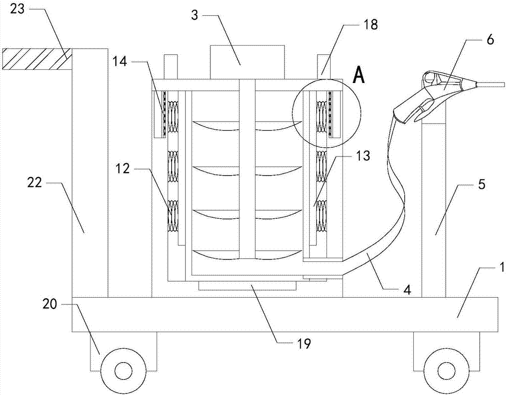
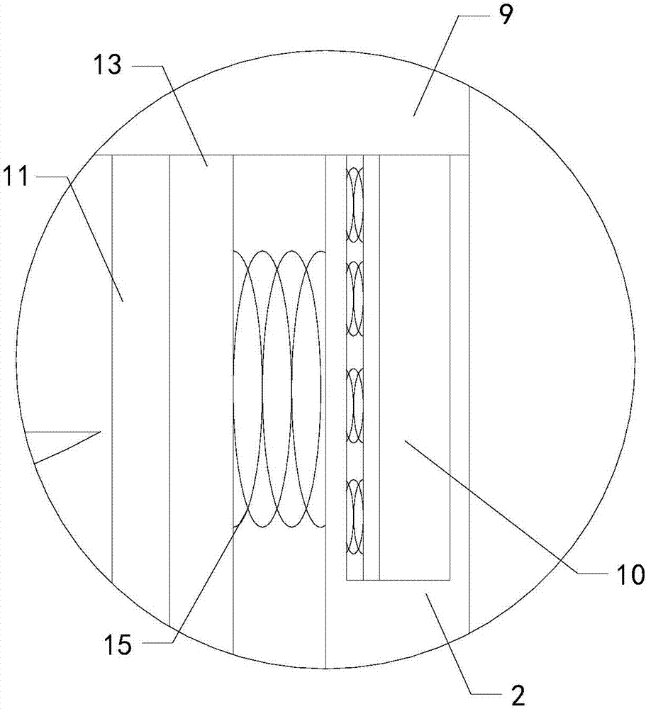
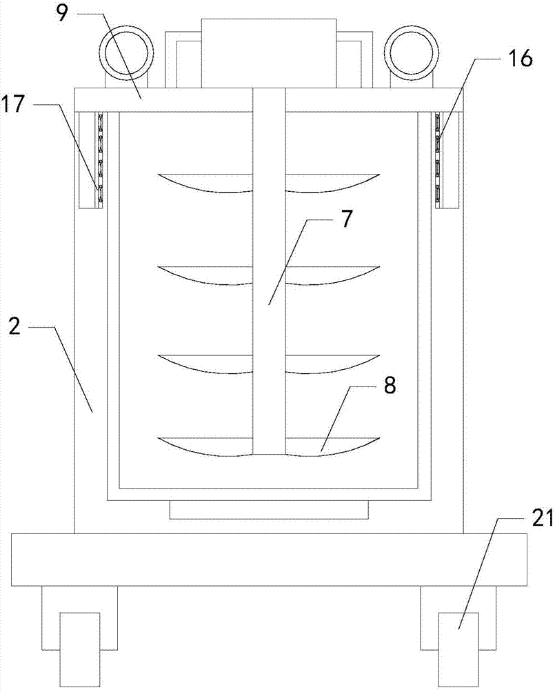
[0016] Such as Figure 1 to Figure 3 As shown, a spraying equipment for a backlight assembly of the present invention includes a base 1, a working box 2, a motor 3, a connecting pipe 4, a bracket 5 and a spray gun 6, and the working box and the bracket are respectively arranged on the left and right sides of the top of the base. A working chamber is arranged inside the box, a rotating shaft 7 is arranged on the output end of the bottom of the motor, and a stirring blade 8 is arranged on the rotating shaft, and the stirring blade is located in the working chamber, the spray gun is placed on the top of the bracket, and the input end of the spray gun communicates with the Tu...


PUM


Abstract

The present invention relates to the technical field of painting technology, in particular to a spraying equipment for backlight components, which is not easy to make the paint fall outside the work box, reduces the cleaning amount of the staff; at the same time, it is convenient to clean the place where the paint is stored ;Including a base, a working box, a motor, a connecting pipe, a bracket and a spray gun, a rotating shaft is arranged on the bottom output end of the motor, and a stirring blade is arranged on the rotating shaft, and the spray gun is placed on the top of the bracket; it also includes a cover plate and four sets of The fixed block, the cover plate is placed on the top of the work box, the motor is set on the top of the cover plate, and the four sets of fixed blocks are respectively set on the left side, right side, front side and rear side of the bottom end of the cover plate; it also includes a placement box, a left spring group, The left pallet, the right spring group and the right pallet, the storage box is placed in the working chamber, the left end of the right pallet is in contact with the upper half of the right side wall of the storage box, a through hole is provided on the lower side of the right end of the storage box, and the input end of the communication pipe A sealing sleeve is provided.

Description

technical field [0001] The invention relates to the technical field of painting technology, in particular to a spraying equipment for backlight components. Background technique [0002] As we all know, the spraying equipment for backlight components is an auxiliary device for spraying paint on its components during the processing of backlights, and it is widely used in the field of production and processing; the existing spraying equipment for backlight components includes The base, working box, motor, connecting pipe, bracket and spray gun, the working box and the bracket are respectively arranged on the left and right sides of the top of the base, a working chamber is arranged in the working box, the motor is arranged on the top of the working box, and the bottom output end of the motor is provided with Rotating shaft, and stirring blades are arranged on the rotating shaft, and the stirring blades are located in the working chamber, the top right side of the working box is...

Claims


Application Information

Patent Timeline
Patent Type & Authority Applications(China)
IPC IPC(8): B05B9/01B05B15/00
CPCB05B9/01B05B9/007B05B15/00
Inventor 赵圣铭李彦龙
Owner YANCHENG SANDING ELECTRONICS TECH CO LTD
Why Eureka
Try Eureka