

Tooth extraction forceps for oral surgery
A technology of surgical and extraction forceps, applied in the field of medical equipment, can solve problems such as difficult operation, damage to teeth, and difficulty in quickly pulling out teeth
- Summary
- Abstract
- Description
- Claims
- Application Information
AI Technical Summary
Problems solved by technology
Method used
Image

Examples
specific Embodiment 1
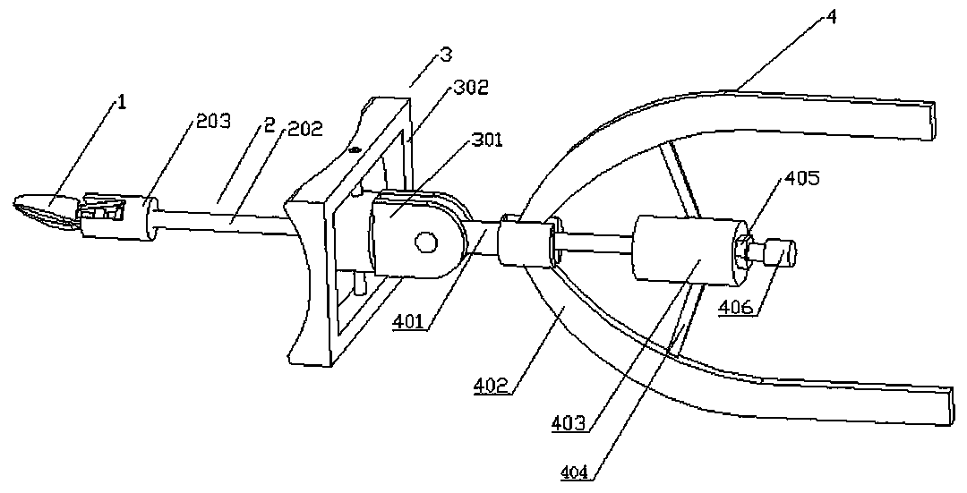
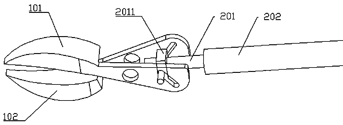
[0027] Specific embodiment 1: This embodiment discloses a tooth extraction forceps for oral surgery, including a beak 1, a transmission device 2, a handle 4 and a support 3, the beak is used to clamp teeth, the beak transmission and the beak 1 connection; the pliers handle is connected to the other end of the transmission device, and remotely controls the opening and closing of the pliers beak 1 and the axial movement of the transmission device
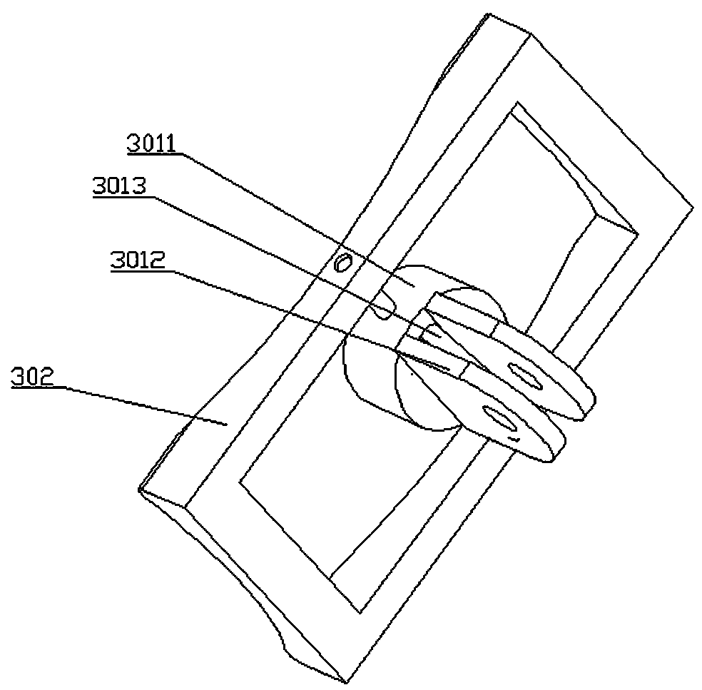
[0028] The support includes a rotating seat 301 and a supporting frame 302 located on the outer layer of the rotating seat. The supporting frame is a hollow structure, and the supporting frame is sleeved on the rotating seat. The outer layer of the rotating seat is provided with a rotating shaft, which is connected to the supporting frame. Through the rotating shaft, the rotating seat can rotate around the axis of the rotating shaft in the hollow of the support frame. The rotating seat includes a rotating block 3011, which is provided ...
PUM
 Abstract
Description
Claims
Application Information