Switching device and application method thereof

A conversion device and piston technology, applied in the direction of workpiece clamping devices, hand-held tools, manufacturing tools, etc., can solve the problems of difficulty and trouble in switching to the unlocked state, and achieve the change of assembly characteristics of loose parts, reduced use, and practicality strong effect

Pending Publication Date: 2017-11-24
XIAN NORTH ELECTRO OPTIC TECH DEFENSE
View PDF13 Cites 2 Cited by
  • Summary
  • Abstract
  • Description
  • Claims
  • Application Information

AI Technical Summary

Problems solved by technology

[0006] In order to solve the technical problem that the process lock and unlock device of the existing series of miniaturized products switches from the unlocked state to the locked state, and the product is extremely difficult and cumbersome to switch from the locked state to the unlocked state at low temperature, the purpose of the present invention is to provide a conversion Device and method of use thereof, enabling the product to be easily and quickly switched between locked and unlocked states

Method used


Image

  • Switching device and application method thereof
  • Switching device and application method thereof
  • Switching device and application method thereof

Examples


Embodiment 1

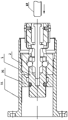
[0033] See figure 1 , the conversion device provided by the embodiment of the present invention includes a piston 1, a first sleeve 2, a pull rod 3 and an elastic limiter 6; the piston 1 and the first sleeve 2 are arranged inside and outside the joint; the The pull rod 3 is movably arranged in the piston 1 and the first sleeve 2; the piston 1, the first sleeve 2 and the pull rod 3 enclose a housing chamber 9, and the ball 8 is arranged in the The first sleeve 2 is respectively provided with elastic stoppers 6 for limiting the axial position of the pull rod 3 on both sides of the pull rod 3 .

[0034] Working principle: the piston 1 is connected with the first sleeve 2 through threads, so as to realize the connection between the gyro mechanism and the acceleration mechanism with a certain pre-tightening force, so that the product is in a locked state. When the rear end face of the pull rod 3 is subjected to the impact force of the striker 10 of the master adjustment platform, ...

Embodiment 2

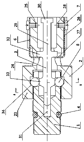
[0038] On the basis of Example 1, such as figure 1 , 2 as well as Figure 4 As shown, the piston 1 is a hollow structure with one end open, which includes a first end face 1 and a second end face 12 oppositely disposed; and an outer face 13 connecting the first end face 1 and the second end face 12 .

[0039] Such as Figure 5 As shown, the first end surface 1 is recessed with a first axial hole 14 toward the direction of the second end surface 12 . The piston 1 has a radial hole 15 recessed inward from its outer surface 13; the radial hole 15 communicates with the first axial hole 14, and a part of the ball 8 is located in the radial hole 15, The pull rod 3 passes through the first axial hole 14 .

[0040] Such as Figure 5 As shown, the first axial hole 14 is composed of a first straight hole 16 , a first tapered hole 17 , a second straight hole 18 and a second tapered hole 19 connected in sequence. The diameter of the first straight hole 16 is larger than the diameter...

Embodiment 3

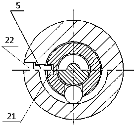
[0043] On the basis of Example 2, such as figure 2 , image 3 As shown, the outer surface 13 of the piston 1 is provided with a limiting groove 21 inwardly recessed near the first end surface 1; the first sleeve 2 is provided with a limiting hole 22 passing through it in the radial direction. The limiting groove 21 is connected with the limiting hole 22 through the first fastener 5 .

[0044] The first fastener 5 is a screw or a pin or the like.

[0045] The present invention connects the piston 1 and the first bushing 2 through the first fastener 5, so that the piston 1 and the first bushing 2 do not rotate relative to each other in the radial direction but follow the movement. Upward produces a limiting effect. On the one hand, the conversion device as a whole moves in the axial direction so that the product enters the locked state; on the other hand, after the product is unlocked after the general adjustment platform is detected, although the piston 1 and the first slee...


PUM


Abstract

The invention relates to a switching device. The switching device comprises a piston, a first sleeve, a pull rod and elastic limiting pieces; the first sleeve is externally arranged at the joint of the piston rod with the first sleeve in a sleeving mode; the pull rod is movably arranged in the piston and the first sleeve; a containing cavity is defined by the piston, the first sleeve and the pull rod, and spheres are arranged in the containing cavity; and the elastic limiting pieces used for limiting the axial position of the pull rod are arranged on the positions, at the two sides of the pull rod, of the first sleeve correspondingly. According to the switching device, the knocked-down part assembly characteristic of an existing technology locking-unlocking device is changed, the integration of the dismounting and mounting processes is achieved, use of auxiliary tools in reduced, the practicability is high, the purpose of rapidly dismounting and mounting winding of a miniaturized product is achieved, one-time dismounting and mounting can be completed only with three minutes, and the working efficiency is enhanced about three times than the original working efficiency.

Description

technical field [0001] The invention relates to the technical field of photoelectric detection, in particular to a conversion device and a use method thereof. Background technique [0002] The existing process locking and unlocking device is mainly used in the gyro mechanism of a series of miniaturized products. The locking and unlocking of the gyro mechanism is realized through the process locking and unlocking device, and then the function of switching the product from the flying state to the working state is realized. Due to the frequent switching between locking and unlocking during the general adjustment of the product, if the product's process locking and unlocking device is directly used as a method of working state conversion, it will inevitably make the final locking and unlocking function of the product unreliable. At the same time, due to the structural characteristics of the series of miniaturized product process locking and unlocking devices, it is extremely dif...

Claims


Application Information

Patent Timeline
Patent Type & Authority Applications(China)
IPC IPC(8): B25B27/14B25B11/02
CPCB25B11/02B25B27/14
Inventor 雒普科曹尔聪胡小波温卫东王秀琴卫娜徐艳张航
Owner XIAN NORTH ELECTRO OPTIC TECH DEFENSE
Why Eureka
Try Eureka