
Road roller capable of cleaning pavement in advance

A technology of road rollers and rollers, applied in the field of road rollers, which can solve problems such as blockage of internal parts of the road roller, uneven road surface rolling, and pressure adjustment, so as to facilitate rolling, prevent road surface rolling unevenness, and prolong the service life.

Inactive Publication Date: 2017-11-24
刘丽
View PDF13 Cites 10 Cited by
  • Summary
  • Abstract
  • Description
  • Claims
  • Application Information

AI Technical Summary

Problems solved by technology

[0004] The purpose of the present invention is to provide a road roller that can clear the road surface in advance to solve the problem that the existing road rollers in the market need to clean the ground before rolling the road surface, otherwise debris and road surface rolling will be caused. Together, it affects the appearance of the road surface; and when it is necessary to increase the weight of the roller to adjust the rolling effect, iron sand or water is often put into the roller to increase the pressure, which is time-consuming and inconvenient. Adjust the pressure at any time according to the demand, resulting in unsatisfactory road rolling effect; and the unsolidified mixture on the road surface will stick to the surface of the roller, resulting in uneven rolling of the road surface; and the mixture driven by the rotation of the tire will be mixed in the road roller. Inside, if it is not cleaned in time, it will cause the internal parts of the road roller to be blocked, which will affect the service life of the road roller

Method used


Image

  • Road roller capable of cleaning pavement in advance
  • Road roller capable of cleaning pavement in advance
  • Road roller capable of cleaning pavement in advance

Examples


Embodiment Construction

[0018] The following will clearly and completely describe the technical solutions in the embodiments of the present invention with reference to the accompanying drawings in the embodiments of the present invention. Obviously, the described embodiments are only some, not all, embodiments of the present invention. Based on the embodiments of the present invention, all other embodiments obtained by persons of ordinary skill in the art without making creative efforts belong to the protection scope of the present invention.

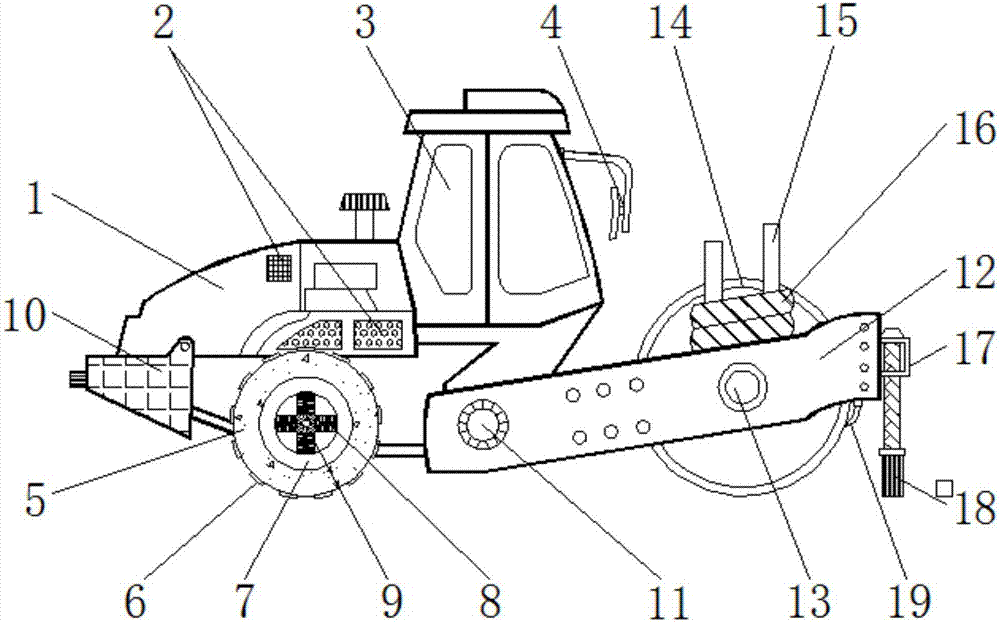
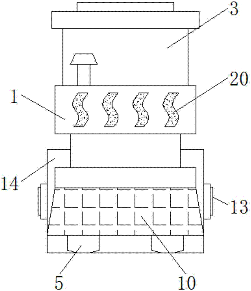
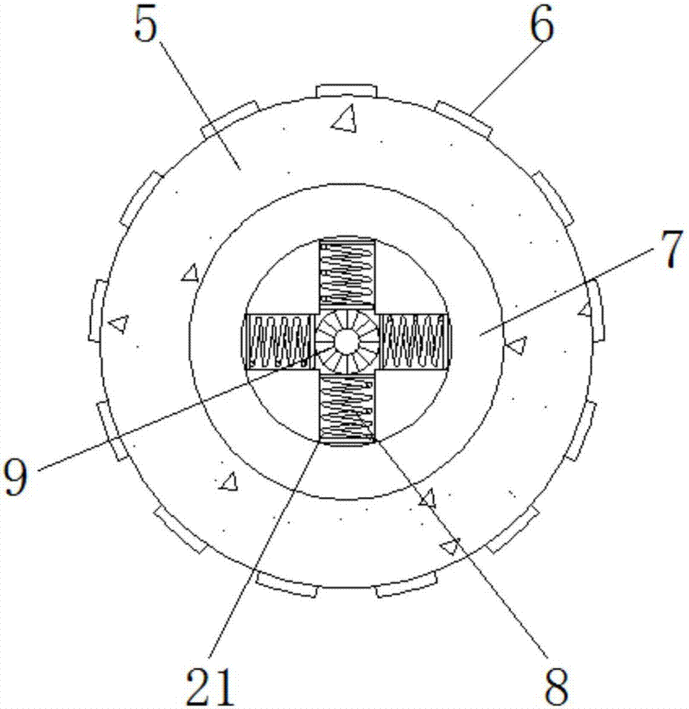
[0019] see Figure 1-5 , the present invention provides a technical solution: a road roller that can clear the road surface in advance, including a housing 1, a cooling hole 2, an operating room 3, a rearview mirror 4, a walking wheel 5, an anti-slip texture 6, an inner wheel 7, and a buffer spring 8. Connecting shaft 9, water retaining shell 10, rotating shaft 11, support rod 12, fixed shaft 13, pressure roller 14, fixed column 15, pressure plate 16, fixed gr...


PUM


Abstract

The invention discloses a road roller capable of cleaning a pavement in advance. The road roller comprises a shell, traveling wheels and a supporting rod, wherein the outer surface of the shell is provided with a heat dissipation hole, an operating room is fixed in front of the shell, the front left side and the front right side of the operating room are respectively provided with a rearview mirror, an inner wheel is installed inside the traveling wheel, a connecting shaft is fixed inside the inner wheel, a junction between the supporting rod and the shell is provided with a rotating shaft, the lower front side of the shell is fixedly provided with the supporting rod, a pressure roller is installed between two adjacent supporting rod, a junction between the pressure roller and the supporting rod is provided with a fixed shaft, a fixed column is welded above the supporting rod, the periphery of the fixed column is sleeved with a pressurizing disc, a fixed trough is arranged in front of the supporting rod, and a cleaning brush is installed below the fixed trough. The number of the pressurizing discs fixed on the fixed column of the road roller capable of cleaning the pavement in advance can be increased according to the requirement, so that the weight of the pressure roller can be adjusted conveniently at any time, and the pavement of different materials can be more conveniently rolled.

Description

technical field [0001] The invention relates to the technical field of construction equipment, in particular to a road roller capable of clearing road surfaces in advance. Background technique [0002] Road rollers belong to the category of road equipment in construction machinery. They are widely used in the filling and compaction operations of large-scale engineering projects such as high-grade highways, railways, airport runways, dams, and stadiums. They can roll sandy, semi-cohesive and cohesive soils, The roadbed stabilized soil and asphalt concrete pavement layer are suitable for various compaction operations by the gravity of the machine itself, so that the rolled layer can be permanently deformed and compacted. It can be divided into two types: steel wheel type and tire type. Smooth milling, groove milling and sheep foot milling, etc., smooth milling is the most common application, mainly used for compaction of pavement surface layer, adopts mechanical or hydraulic t...

Claims


Application Information

Patent Timeline
Patent Type & Authority Applications(China)
IPC IPC(8): E01C19/26E01C19/23
CPCE01C19/26E01C19/238
Inventor 刘丽张莉张萌
Owner 刘丽
Learn More