Circuit fault detecting method using chaotic power supply source current
What is AI technical title?
AI technical title is built by Patsnap AI team. It summarizes the technical point description of the patent document.
A technology for power supply current and circuit faults, which is used in electronic circuit testing, components of electrical measuring instruments, and electrical measurement. Effect
Inactive Publication Date: 2017-12-01
SUZHOU UNIV
View PDF6 Cites 1 Cited by
Summary
Abstract
Description
Claims
Application Information
AI Technical Summary
This helps you quickly interpret patents by identifying the three key elements:
Problems solved by technology
Method used
Benefits of technology
Problems solved by technology
[0004] For example, the current test technology of CMOS circuit has applied the quiescent current I of the main circuit of the DC power supply. ddq and dynamic current I ddt , and achieved a good performance of nearly 80% fault coverage, however, there are generally problems in the use process that the difference is not obvious enough and the positioning is not accurate enough
Method used
Image
Click on the blue label to locate the original text in one second.
Reading with bidirectional positioning of images and text.
Examples
Embodiment 1
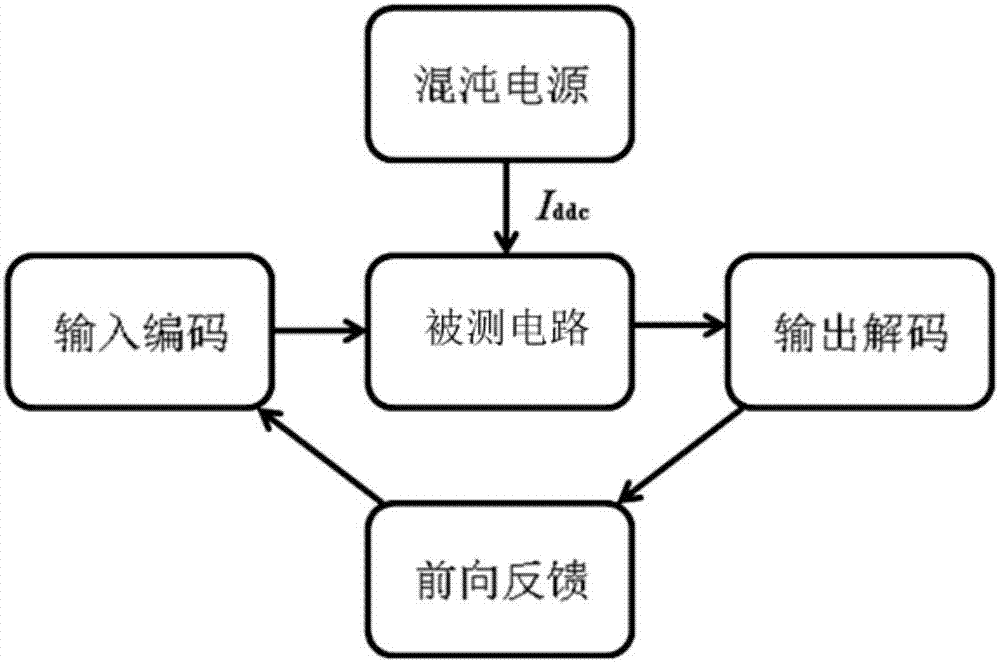
[0036] see Figures 1 to 7 As shown, a chaotic power supply current method for circuit fault detection includes the following steps:
[0037] Step 1, using a chaotic circuit as the power supply of the circuit under test;
[0038] Step 2, using the dry circuit current of the chaotic circuit to code the fault of the circuit under test, and inputting it into the circuit under test;
[0039] Step 3: Decode the output of the circuit under test, and the obtained fault characteristics correspond to the input faults one by one to form a fault dictionary;
[0040] An up-sampling circuit and a down-sampling circuit are respectively provided at both ends of the tested circuit.
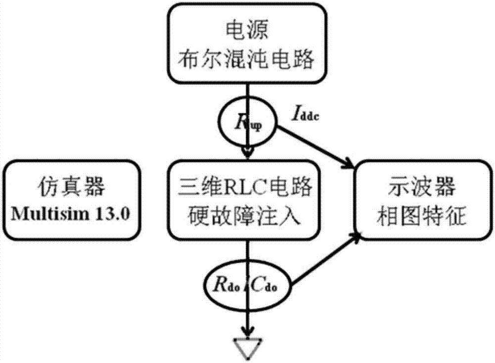
[0041] In this embodiment, the fault difference judgment may further extract fault features, such as extreme values or complexity indexes, from the recorded data strings of main circuit current parameters of the chaotic power supply.
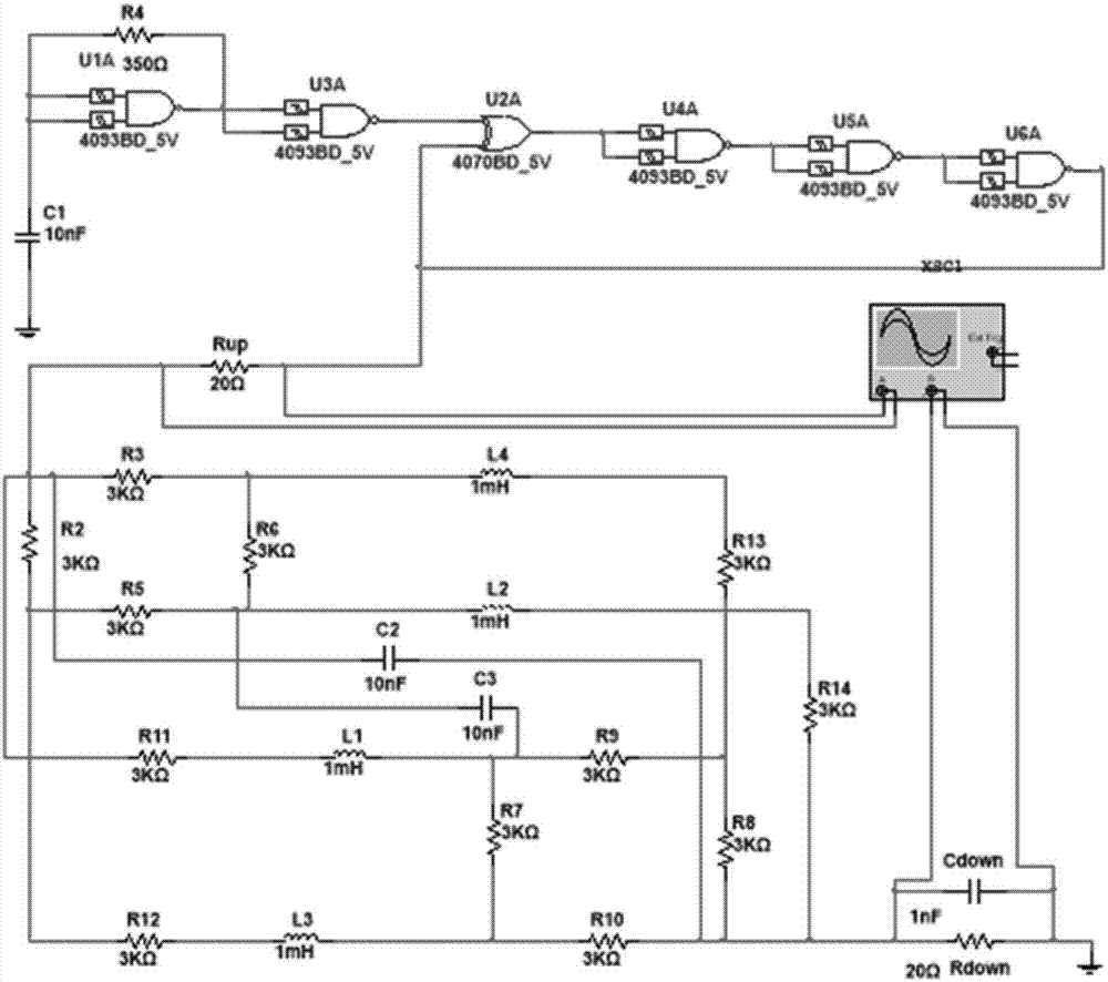
[0042] The chaotic circuit is a Boolean chaotic circuit, the main paramet...
Embodiment 2
[0050] see figure 1 , 8 As shown in and 9, a chaotic power supply current method for circuit fault detection includes the following steps:
[0051] Step 1, using a chaotic circuit as the power supply of the circuit under test;
[0052] Step 2, using the dry circuit current of the chaotic circuit to code the fault of the circuit under test, and inputting it into the circuit under test;
[0053] Step 3: Decode the output of the circuit under test, and the obtained fault characteristics correspond to the input faults one by one to form a fault dictionary;
[0054] An up-sampling circuit and a down-sampling circuit are respectively provided at both ends of the tested circuit.
[0055] In this embodiment, the fault difference judgment may further extract fault features, such as extreme values or complexity indexes, from the recorded data strings of main circuit current parameters of the chaotic power supply.
[0056] The chaotic circuit is Chua's chaotic circuit, the main par...
PUM
Abstract
The present invention discloses a circuit fault detecting method using chaotic power supply source current, comprising the following steps: step 1: using a chaotic circuit as a power supply source for a tested circuit; step 2: applying the trunk current of the chaotic circuit to encode the fault of the tested circuit and inputting the tested circuit; and step 3: decoding the output of the tested circuit, wherein the obtained fault characteristics correspond to the inputted fault one by one to form a fault dictionary and the two ends of the tested circuit are provided with an upsampling circuit and a downsampling circuit respectively. According to the invention, through the constructing of a chaotic modulation power supply source and the defining of the trunk current parameters of the chaotic power supply source, it is possible to realize the detection of the circuit fault and to achieve the advantages of direct graphic solution and obvious contrasts as well as accurate fault location.
Description
technical field [0001] The invention relates to a circuit fault detection method, in particular to a chaotic power supply current method for circuit fault detection, which aims at extracting the characteristic differences of main fault types by using the chaotic measurement technology and applying the main circuit current parameters of the chaotic power supply. Background technique [0002] The ratio of soft faults and hard faults of analog circuits basically conforms to the 20 / 80 law. Among them, the hard fault means that the parameters of the faulty component suddenly change greatly, mainly including short circuit and open circuit; the soft fault means that the parameter value of the component deviates to an unacceptable degree with time or environmental conditions, exceeding the tolerance of the component parameter scope. [0003] The mainstream method of fault detection in existing analog circuits is to firstly inject faults into the circuit under test in the emulator, ...
Claims
Application Information
Patent Timeline
Application Date:The date an application was filed.
Publication Date:The date a patent or application was officially published.
First Publication Date:The earliest publication date of a patent with the same application number.
Issue Date:Publication date of the patent grant document.
PCT Entry Date:The Entry date of PCT National Phase.
Estimated Expiry Date:The statutory expiry date of a patent right according to the Patent Law, and it is the longest term of protection that the patent right can achieve without the termination of the patent right due to other reasons(Term extension factor has been taken into account ).
Invalid Date:Actual expiry date is based on effective date or publication date of legal transaction data of invalid patent.

