Robot equipment

A technology of robots and equipment, which is applied in the field of robots, can solve problems such as the failure of automatic ejection of contacts, unstable power supply connections, and damage to robots, and achieve simple and convenient operation of unlocking contacts, convenient and labor-saving pull-out of contacts, and simple and convenient operation Effect

Inactive Publication Date: 2017-12-05
朱鸿杰
View PDF5 Cites 13 Cited by
  • Summary
  • Abstract
  • Description
  • Claims
  • Application Information

AI Technical Summary

Problems solved by technology

[0002] At present, the charging of the robot is mainly to insert the contacts connected with the robot directly into the power inlet slot of the power inlet body. Although this cooperation method is simple to operate, the contacts can still be pulled out directly after being inserted into the power inlet slot. When kicking by mistake hits the cable connected between the contact and the robot, it will cause the contact to detach from the power supply slot, resulting in a sudden power failure of the robot. Therefore, the existing cooperation method exists The risk of unstable power supply connection is likely to cause damage to the robot due to sudden power failure, and the existing contact cannot pop out automatically, and a large force needs to be applied when the contact is pulled out, which is laborious to pull out

Method used


Image

  • Robot equipment
  • Robot equipment
  • Robot equipment

Examples


Embodiment Construction

[0019] The preferred embodiments of the present invention will be described in detail below in conjunction with the accompanying drawings, so that the advantages and features of the present invention can be more easily understood by those skilled in the art, so as to define the protection scope of the present invention more clearly.

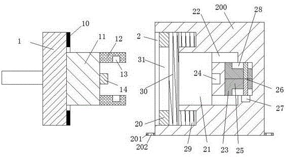
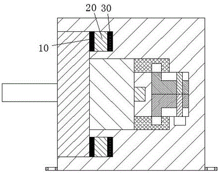
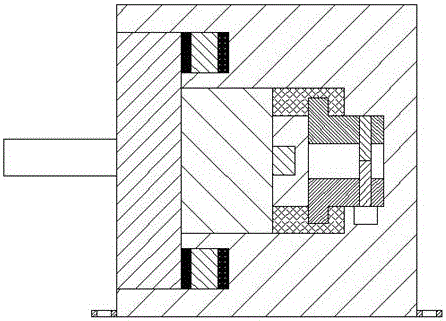
[0020] refer to Figure 1-4 The shown robot equipment includes a connecting body and a charging body, the connecting body includes a first insertion rod 1 and a second insertion rod 11, and the second insertion rod 11 is arranged on the first insertion rod 1, the middle part of the right end surface of the second insertion rod 11 is provided with a contact 14, and the front and rear ends of the right end surface of the second insertion rod 11 are respectively provided with two plates 12 correspondingly, and the two plates Two locking holes 13 are provided correspondingly on the inner end surface of the member 12, and an annular spacer 10 is provi...


PUM


Abstract

The invention discloses robot equipment. The robot equipment comprises an electric connection body and an electric feeding body. The electric connection body comprises a first plugging rod and a second plugging rod. The second plugging rod is disposed on the middle part of the right end surface of the first plugging rod, and the middle part of the right end surface of the second inserting rod is provided with a contact. The front end and the rear end of the right end surface of the second plugging rod are symmetrically provided with two plate members, and the inner side end surfaces of the two plate members are respectively and symmetrically provided with two locking holes. Annular cushion blocks are disposed on the right end surface of the first plugging rod and the outer ring of the second plugging rod. The electric feeding body comprises a base. The robot equipment is advantageous in that a structure is simple, and power supply stability is good; the operation of the whole device is safe and reliable, and a structural design is reasonable, and even when a cable used for connection between the contact and the robot is accidentally kicked and collided by people, the contact is prevented from being disengaged from cooperated connection with an electric feeding groove, and therefore the locking operation and the unlocking operation of the contact are simple and convenient, and popularization and application are facilitated.

Description

technical field [0001] The invention relates to the field of robots, in particular to a robot device. Background technique [0002] At present, the charging of the robot is mainly to insert the contacts connected with the robot directly into the power inlet slot of the power inlet body. Although this cooperation method is simple to operate, the contacts can still be pulled out directly after being inserted into the power inlet slot. When kicking by mistake hits the cable connected between the contact and the robot, it will cause the contact to detach from the power supply slot, resulting in a sudden power failure of the robot. Therefore, the existing cooperation method exists The risk of unstable power supply connection is likely to cause damage to the robot due to sudden power failure. In addition, the contacts in this matching method cannot automatically pop out, and a large force needs to be applied when the contacts are pulled out, which is laborious to pull out. Conte...

Claims


Application Information

Patent Timeline
Patent Type & Authority Applications(China)
IPC IPC(8): H01R13/629H01R13/633H01R13/639H01R43/26B25J19/00
CPCB25J19/00H01R13/629H01R13/633H01R13/639H01R43/26
Inventor 朱鸿杰
Owner 朱鸿杰
Why Eureka
Try Eureka