
Vibration-resistant electromagnet

A technology of electromagnets and magnetic blocks, which can be used in the direction of electromagnets with armatures, electromagnets, locks operated by non-mechanical transmission, etc., and can solve problems such as poor safety

Pending Publication Date: 2018-01-16
惠州市亚欣科技有限公司
View PDF8 Cites 3 Cited by
  • Summary
  • Abstract
  • Description
  • Claims
  • Application Information

AI Technical Summary

Problems solved by technology

[0002] Existing electromagnets used for shared charging treasure cabinets are kept in the maximum exposed self-locking state under the action of spring force after power failure. When subjected to an instantaneous axial impact external force, the spring will be compressed and retracted, resulting in unlocking and poor safety.

Method used


Image

  • Vibration-resistant electromagnet
  • Vibration-resistant electromagnet
  • Vibration-resistant electromagnet

Examples


Embodiment Construction

[0013] The following will clearly and completely describe the technical solutions in the embodiments of the present invention with reference to the drawings in the embodiments of the present invention, but this does not limit the protection scope of the present invention.

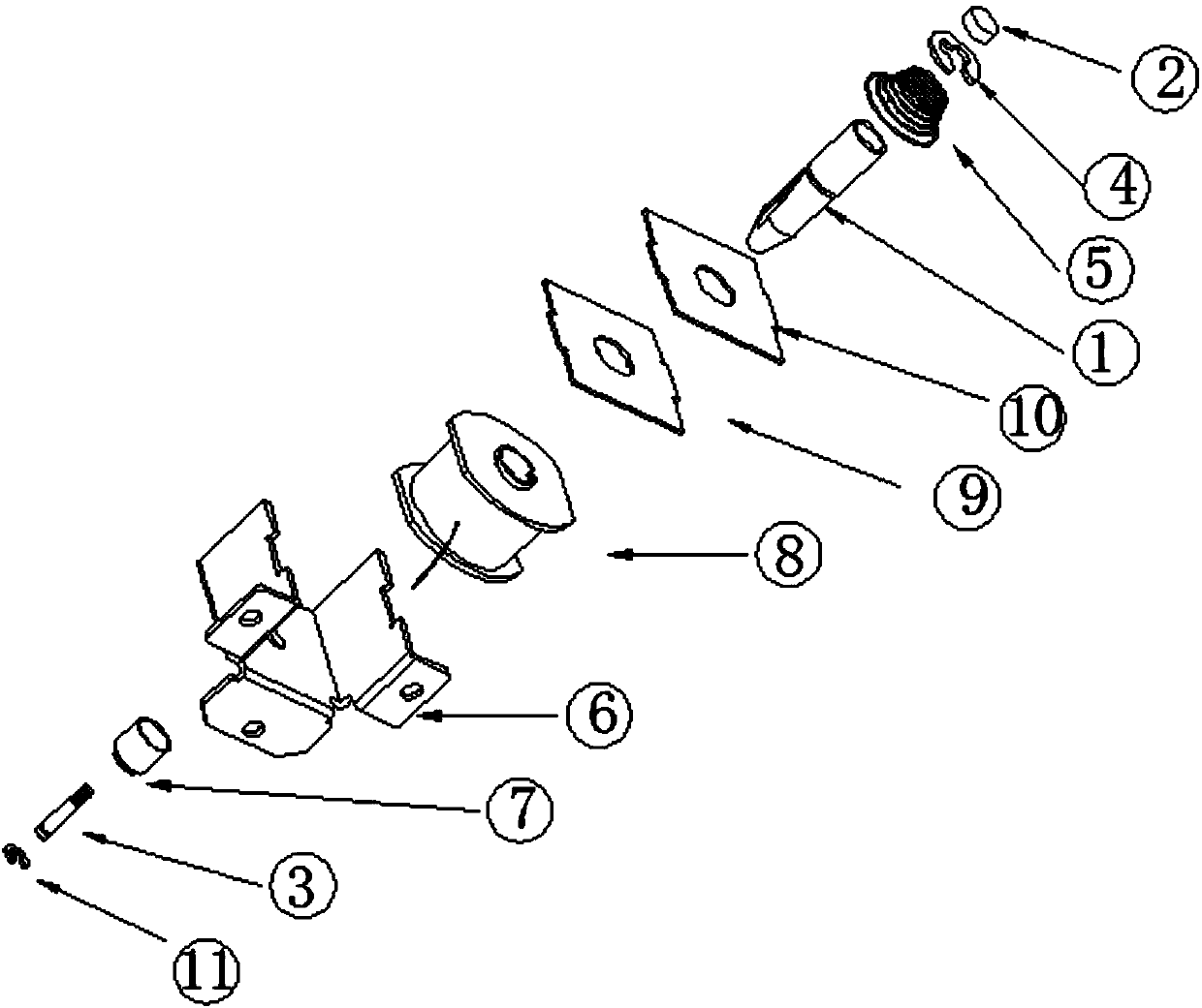
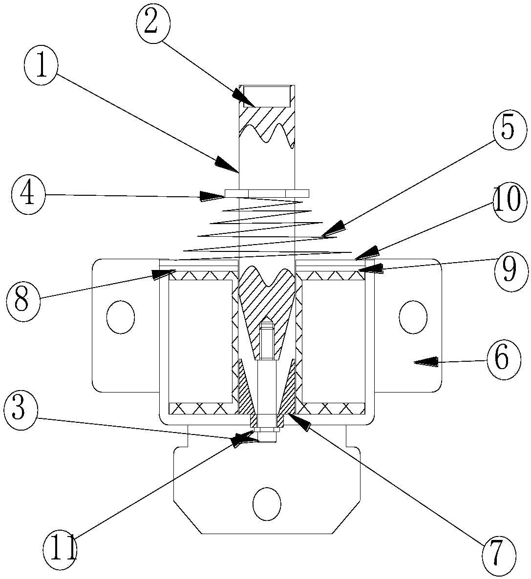
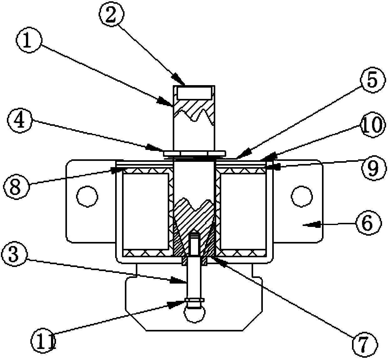
[0014] Such as figure 1 As shown, an anti-vibration electromagnet includes a magnetic block 2, an upper collar 4, a spring 5, a slide rod 1, a first cover plate 10, a second cover plate 9, a coil 8, and a casing 6 connected sequentially from top to bottom. , iron core 7, ejector rod 3, and lower collar 11, wherein the spring 5 and the upper collar 4 are sleeved on the upper part of the slide bar 1, and the magnetic block 2 is installed on the upper end of the slide bar 1, The lower part of the slide bar 1 passes through the first and second cover plates 10, 9 and the coil 8 and is installed in the housing 6 together with the first and second cover plates 10, 9 and the coil 8, The push rod 3 is connected to...


PUM


Abstract

The invention discloses a vibration-resistant electromagnet. The vibration-resistant electromagnet comprises a magnet block, an upper clamping ring, a spring, a slide rod, a first cover plate, a second cover plate, a coil, a shell, an iron core, an ejector pin and a lower clamping ring, wherein the magnet block, the upper clamping ring, the spring, the slide rod, the first cover plate, the secondcover plate, the coil, the shell, the iron core, the ejector pin and the lower clamping ring are connected in sequence from top to bottom. A spiral groove is formed in the lateral side of the slide rod, and lugs matched with the spiral groove are arranged at a through hole of the second cover plate. When the electromagnet vibrates, the spiral groove in the lateral side of the slide rod makes contact with the lugs, and inverted repulsion is generated, so that the slide rod is prevented from continuing to move downwards. When the electromagnet vibrates in a power-off state, the spiral groove inthe lateral side of the slide rod instantaneously makes contact with the lugs on the inner side of the cover plate, and the inverted repulsion is generated, so that the slide rod is prevented from continuing to move downwards. When an original electromagnet suffers from instantaneous axial external impact force, the spring can be compressed to retract, so that an unlocking problem is generated, but the problem is solved by means of the vibration-resistant electromagnet.

Description

technical field [0001] The invention relates to an anti-seismic electromagnet used for a shared power bank cabinet. Background technique [0002] Existing electromagnets used for shared charging treasure cabinets are kept in the maximum exposed self-locking state under the action of spring force after power failure. When subjected to an instantaneous axial impact external force, the spring will be compressed and retracted, resulting in unlocking and poor safety. . Contents of the invention [0003] The object of the present invention is to provide a shockproof electromagnet with good safety and self-locking function. [0004] In order to solve the above technical problems, the technical solution adopted by the present invention is: an anti-vibration electromagnet, including a magnetic block connected in sequence from top to bottom, an upper collar, a spring, a slide bar, a first cover plate, a second cover plate, Coil, casing, iron core, push rod, lower collar, wherein, ...

Claims


Application Information

Patent Timeline
IPC IPC(8): E05B47/00E05B65/52H01F7/16
Inventor 周向东
Owner 惠州市亚欣科技有限公司
Learn More