
Mechanical logic device and mechanical digital input device and digital lock with the mechanical logic device

A technology of mechanical logic and input device, applied in mechanical control devices, locks operated by mechanical transmission, devices to prevent/restrict/restore the movement of parts of control mechanisms, etc. Complexity and other problems, to achieve the effect of expanding the usable range, satisfying the unlocking safety, and expanding the application range

Active Publication Date: 2016-11-02
高瞩宇
View PDF5 Cites 0 Cited by
  • Summary
  • Abstract
  • Description
  • Claims
  • Application Information

AI Technical Summary

Problems solved by technology

[0002] The same digital input of the mechanical digital lock is a difficult problem, and the continuous input of the same digital is even more difficult, as the mechanical logic digital lock provided by the invention patent (PCT / CN2004 / 000529) applied by the inventor can realize the continuous input of the same digital, However, its complex structure, high manufacturing cost, and large volume limit the application of this mechanical logic device. For example, it cannot be used in conjunction with an electronic key lock input mechanism. There is no mechanical digital mechanism and electronic digital mechanism that can use the same set of buttons. for digital input
[0003] In addition, there are many applications of electronic locks at present, which can be remotely controlled and easy to change passwords, but there are also insurmountable reliability problems. For example, public electronic door locks cannot be opened when the power is off or malfunctions; Password lock screen is often used for protection, because it can be deciphered by electronic password cracker, so the important data in the computer still has security problems

Method used


Image

  • Mechanical logic device and mechanical digital input device and digital lock with the mechanical logic device
  • Mechanical logic device and mechanical digital input device and digital lock with the mechanical logic device
  • Mechanical logic device and mechanical digital input device and digital lock with the mechanical logic device

Examples


Embodiment 1

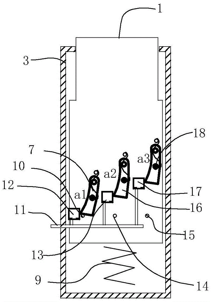
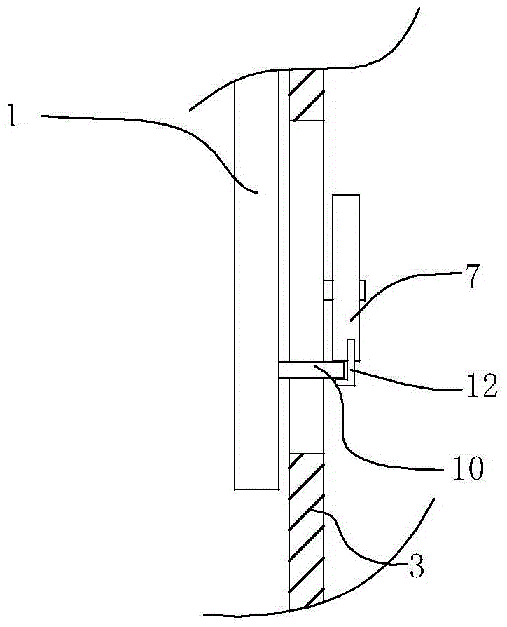
[0043] Figure 1a It is a schematic diagram of the mechanical logic device of the present invention, the mechanical logic device includes a mixed double-bit device, and the mixed double-bit device is a column-type mixed double-bit device, including a housing 3, and the housing 3 has a cylinder of movable parts 1. The cylinder 1 can move up and down in the housing 3, the top of the cylinder 1 protrudes from the top opening of the housing 3, and there is a shoulder on the cylinder 1, which can be stuck on the housing 3 The inside of the top opening restricts the cylinder 1 from coming out of the housing 3 completely. A spring is provided below the cylinder 1 so that the cylinder 1 has a tendency to be positioned upward at the set position, which is the position where the shoulder of the cylinder 1 is stuck on the top opening of the housing 3, The cylinder 1 also has a reset position, that is, the initial position of the cylinder 1 , which is the position when the cylinder 1 is l...

Embodiment 2

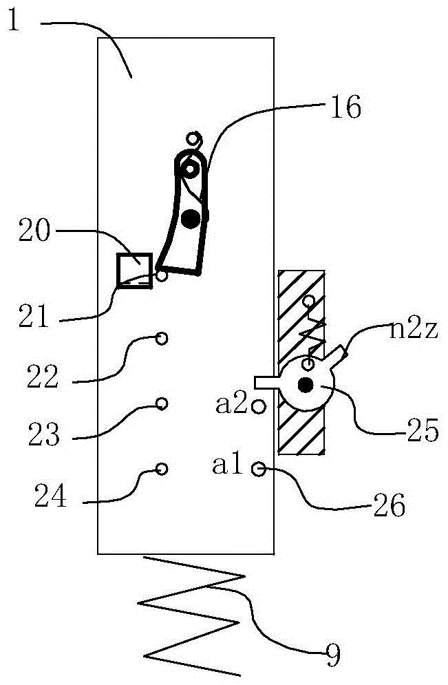
[0047] figure 2 It is another method of column-type mixed double-position device. In this method, the structure of the column body 1 and the housing 3 is the same as that of the embodiment 1. The difference is that in the direction of movement of the column body 1, the pins of the locking parts are arranged in sequence. 21, 22, 23 and 24, a latch locking mechanism 16 is arranged on the housing, and the locking mechanism 16 can lock the composition number 1 digit, number 2 digits, number 3 digits and 4 digits constitute the locking mechanism of the corresponding digits. The power input end 20 has the same structure as one of the power input ends in Fig. 1, and it only applies force to the locking mechanism 16. When the cylinder is in the number 1 position, push the power input end 20 to the right, and the power input end 20 crosses the column pin 21 and Pushing the locking mechanism unlocks the cylinder 1, the column pin 22 slides to the locking mechanism 16, and the input en...

Embodiment 3

[0050] Figure 3a It is another embodiment of a mixed double-position device, which includes a pin-type combined locking mechanism, Figure 3b It is a left view, the housing 3 of the mixed double-position device has locking holes h1 and h2 arranged at intervals along the vertical direction of the movement direction of the cylinder 1, and the cylinder 1 has pin locking mechanisms 31, 32, 33, 34, The pin locking mechanisms 31, 33, 32, 34 are respectively distributed in the same vertical direction of the locking holes h1 and h2, and the pin locking mechanisms 31, 32, 33, and 34 are respectively staggered in height. The mechanism and the locking hole respectively constitute a locking mechanism, which can respectively lock the cylinder 1 at the number 1, number 2, number 3 and number 4 positions. The pin locking mechanisms 31, 32, 33 and 34 respectively comprise a groove in the cylinder 1, a pin positioned at the outer end of the groove, and a spring between the pin and the inner ...


PUM


Abstract

A mechanical logic component comprising a mixed dual-position component. The mixed dual-position component comprises a housing (3) and, provided within the housing (3), a movable part (1), a reset mechanism, and locking mechanisms. The housing (3) is provided thereon with power transmitting ends (12, 13, and 17), which input an external force to the locking mechanisms. The locking mechanisms match with the power transmitting ends (12, 13, and 17) to make, when the movable part (1) is moving within the housing (3) and simultaneously as the locking mechanism at a certain position is unlocked, the locking mechanism at the next position to lock the movable part (1) at the next position. Also disclosed are a mechanical digital input device having the mechanical logic component, a mechanical digital lock, and, having the mechanical digital input device, a mechanical digital lock, a mechanical electronic digital lock, and a computer button mechanical digital lock.

Description

technical field [0001] The invention relates to a mechanical logic device, a mechanical digital input device and a digital lock using the mechanical logic device. Background technique [0002] The same digital input of the mechanical digital lock is a difficult problem, and the continuous input of the same digital is even more difficult, as the mechanical logic digital lock provided by the invention patent (PCT / CN2004 / 000529) applied by the inventor can realize the continuous input of the same digital, However, its complex structure, high manufacturing cost, and large volume limit the application of this mechanical logic device. For example, it cannot be used in conjunction with an electronic key lock input mechanism. There is no mechanical digital mechanism and electronic digital mechanism that can use the same set of buttons. for digital input. [0003] In addition, there are many applications of electronic locks at present, which can be remotely controlled and easy to ch...

Claims


Application Information

Patent Timeline
Patent Type & Authority Patents(China)
IPC IPC(8): G05G5/00G05G5/06G05G5/08G05G21/00E05B53/00
CPCE05B49/00G05G5/06G05G5/08
Inventor 高瞩宇
Owner 高瞩宇
Learn More