Device for releasing catcher for refrigerator and freezer

a technology for releasing devices and catcher, which is applied in the direction of hinges, lighting and heating apparatus, and domestic cooling devices, etc. it can solve the problems of unfavorable product and maintenance costs, unfavorable product and service life, and inability to open the door, so as to improve the entire structure of the catcher, avoid a complicated assembling configuration, and expand the range of the catcher.

Inactive Publication Date: 2016-02-25
KONGJIN
View PDF0 Cites 4 Cited by
  • Summary
  • Abstract
  • Description
  • Claims
  • Application Information

AI Technical Summary

Benefits of technology

[0012]It is another object of the present invention to provide a catcher release device for a refrigerator and freezer that improves the entire structure of a catcher in such a manner as to be applied to a variety of door lock devices, thus expanding its available range, and that is applied to a conventional door lock device having no releasing means connected thereto when a person is locked in the refrigerator and freezer, thus solving the problems occurring when the person is locked in the refrigerator and freezer.
[0013]It is yet another object of the present invention to provide a catcher release device for a refrigerator and freezer that avoids a complicate assembling configuration and organic coupling relations for coupling separate releasing means to a door lock device, thus reducing the cost of the product and the maintenance cost of the product.
[0014]It is still another object of the present invention to provide a catcher release device for a refrigerator and freezer that is configured to allow a rotary cam disposed between a base frame and a fixing frame to rotate together with the rotation of an inner handle and a rotary shaft coupled to the inside of a side panel of a door of the refrigerator and freezer and thus to allow a locking member to move backward to rotate a housing fixed to the base frame backward around a hinge shaft, thus opening the door, and that is configured especially to have an elastic member disposed on the interior of the housing and the top portion of the base frame to allow the housing to rapidly rotate around the hinge shaft upon the opening of the door.

Problems solved by technology

In this case, however, the releasing means becomes complicated in a coupling structure, and it is hard to perform the assembling and separating processes thereof, thus undesirably lowering the productivity thereof.
Since the conventional catcher is maintained at the rigidly fixed state to the side panel, the inner handle and the rotary shaft cannot rotate, thus making it impossible to open the door.
The conventional releasing means becomes complicated in the continuously operating configuration through the organic coupling among the trigger, the operating plate, the latch and the finger upon the operation of the inner handle and the rotary shaft, and further, since the releasing means connected to the conventional door lock device has high price, it may be often removed from the door lock device.
Furthermore, the conventional door lock device and the catcher have many difficulties in the whole assembling processes and the maintenance, thus undesirably increasing the cost of the product and the maintenance cost thereof.
The conventional door lock device and the catcher have main problems as follows: firstly, a hinge shaft of the outer handle may be broken in the process of forcibly pulling the outer handle in the state where a user does not recognize the locking state of the outer handle, thus making it hard to operating the latch and failing to rotate the inner handle; and secondly, if a person is locked in the refrigerator and freezer, he or she cannot be escaped therefrom.
The conventional catcher is just fixed to the side panel, but it does not have any separate releasing means, thus being not expanded in the available range thereof.

Method used


Image

  • Device for releasing catcher for refrigerator and freezer
  • Device for releasing catcher for refrigerator and freezer
  • Device for releasing catcher for refrigerator and freezer

Examples


Embodiment Construction

[0024]Hereinafter, an explanation on a catcher release device for a refrigerator and freezer according to the present invention will be in detail given with reference to the attached drawing.

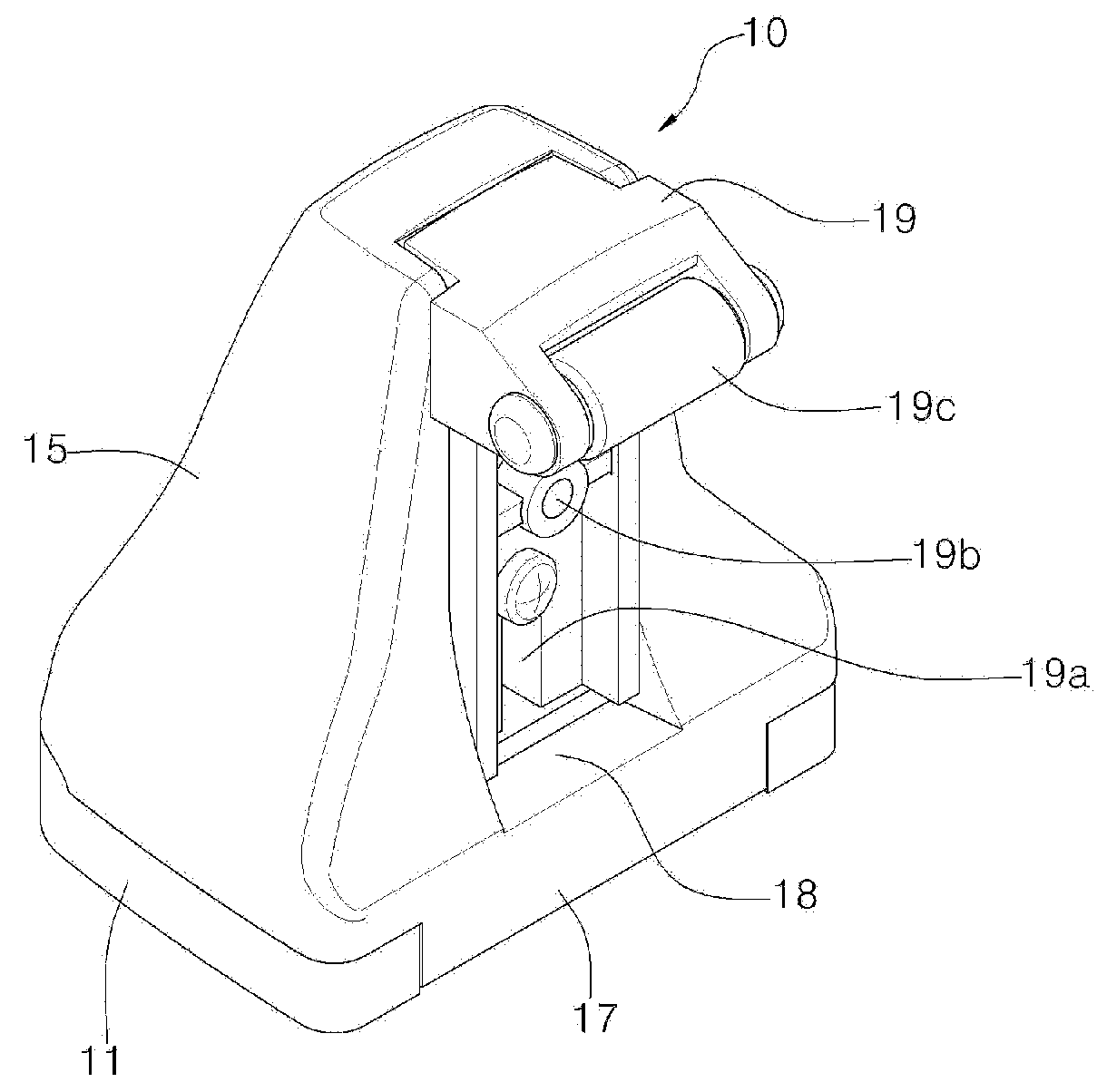
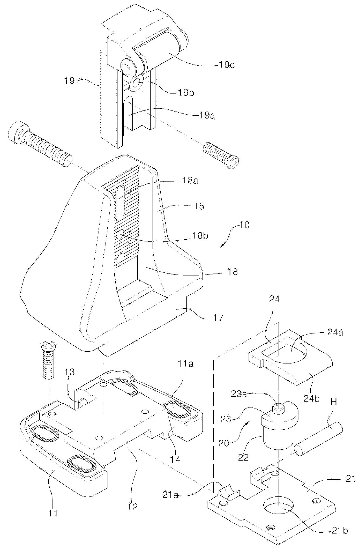
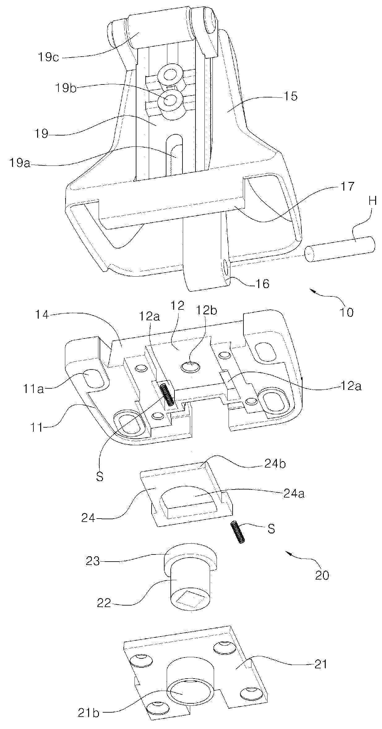
[0025]Referring to FIGS. 1 to 6, a catcher release device for a refrigerator and freezer according to the present invention includes: a catcher 10 having a base frame 11 fixed by means of bolts to a side panel of the refrigerator and freezer, a housing 15 coupled to the top portion of the base frame 11 by means of a hinge shaft H, and a striker 19 fixed to the front surface of the housing 15 by means of bolts; and releasing means 20 having an inner handle 25 and a rotary shaft 26 disposed on the inside of the side panel in such a manner as to be connected to the base frame 11, a rotary cam 22 disposed between the base frame 11 and a fixing frame 21 in such a manner as to rotate together with the rotary shaft 26, a locking member 24 adapted to appear and disappear in accordance with the rotation ...


PUM


Abstract

The present invention relates to a catcher release device for a refrigerator and freezer, and more particularly, to a catcher release device for a refrigerator and freezer that has releasing means disposed on the inside of a side panel on which a catcher is located in such a manner as to be connected to the catcher, so that if a person is locked in the refrigerator and freezer, an inner handle of the releasing means just rotates, irrespective of a door lock device, thus allowing the catcher to be separated from the door lock device to rapidly open a door for the refrigerator and freezer.

Description

BACKGROUND OF THE INVENTION[0001]1. Field of the Invention[0002]The present invention relates to a catcher release device for a refrigerator and freezer, and more particularly, to a catcher release device for a refrigerator and freezer that has releasing means disposed on the inside of a side panel on which a catcher is located in such a manner as to be connected to the catcher, so that if a person is locked in the refrigerator and freezer, an inner handle of the releasing means just rotates, irrespective of a door lock device, thus allowing the catcher to be separated from the door lock device to rapidly open a door for the refrigerator and freezer.[0003]2. Background of the Related Art[0004]Generally, a refrigerator and freezer is used to keep articles to be cooled and frozen therein temporarily or for a long period of time, thus preventing them from being decayed. On the other hand, a door lock device having a case in which a handle and a lock are disposed is mounted on a door pa...

Claims


Application Information

Patent Timeline
Patent Type & Authority Applications(United States)
IPC IPC(8): E05B15/02F25D23/02
CPCF25D23/028E05B15/022E05D3/00E05B15/0245E05B63/246E05B65/0053F25D29/006F25D23/02
Inventor YUN, KYU, JUNG
Owner KONGJIN
Why Eureka
Try Eureka