Bridge erecting machine of double-T-shaped beam bridge

A bridge erecting machine and pillow beam technology, which is applied in the field of bridge erecting machines for double T-beam bridges, can solve problems such as inapplicability, and achieve the effects of clear steps, reduced equipment passing time, and simple operation

Pending Publication Date: 2018-01-19
CHINA RAILWAYS CORPORATION +1
View PDF7 Cites 6 Cited by
  • Summary
  • Abstract
  • Description
  • Claims
  • Application Information

AI Technical Summary

Problems solved by technology

However, because the height of the existing bridge erecting machine can reach 8m during construction, which is seriously over the limit, therefore, under the existing line conditions, the existing bridge erecting machine is convenient for erecting new porous beams after the old beams are removed. Unable to apply, need to propose a new type of bridge erecting machine structure

Method used


Image

  • Bridge erecting machine of double-T-shaped beam bridge
  • Bridge erecting machine of double-T-shaped beam bridge
  • Bridge erecting machine of double-T-shaped beam bridge

Examples


Embodiment Construction

[0022] In order to make the objectives, technical solutions, and advantages of the embodiments of the present invention clearer, the technical solutions in the embodiments of the present invention will be described clearly and completely in conjunction with the accompanying drawings in the embodiments of the present invention. Obviously, the described embodiments It is a part of the embodiments of the present invention, but not all the embodiments. Based on the embodiments of the present invention, all other embodiments obtained by those of ordinary skill in the art without creative work shall fall within the protection scope of the present invention.

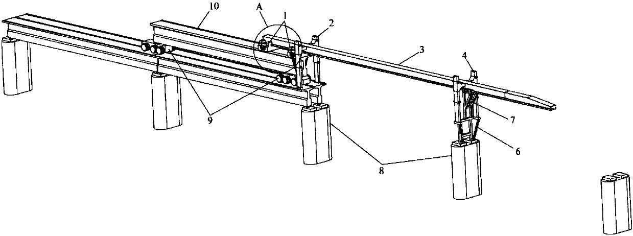
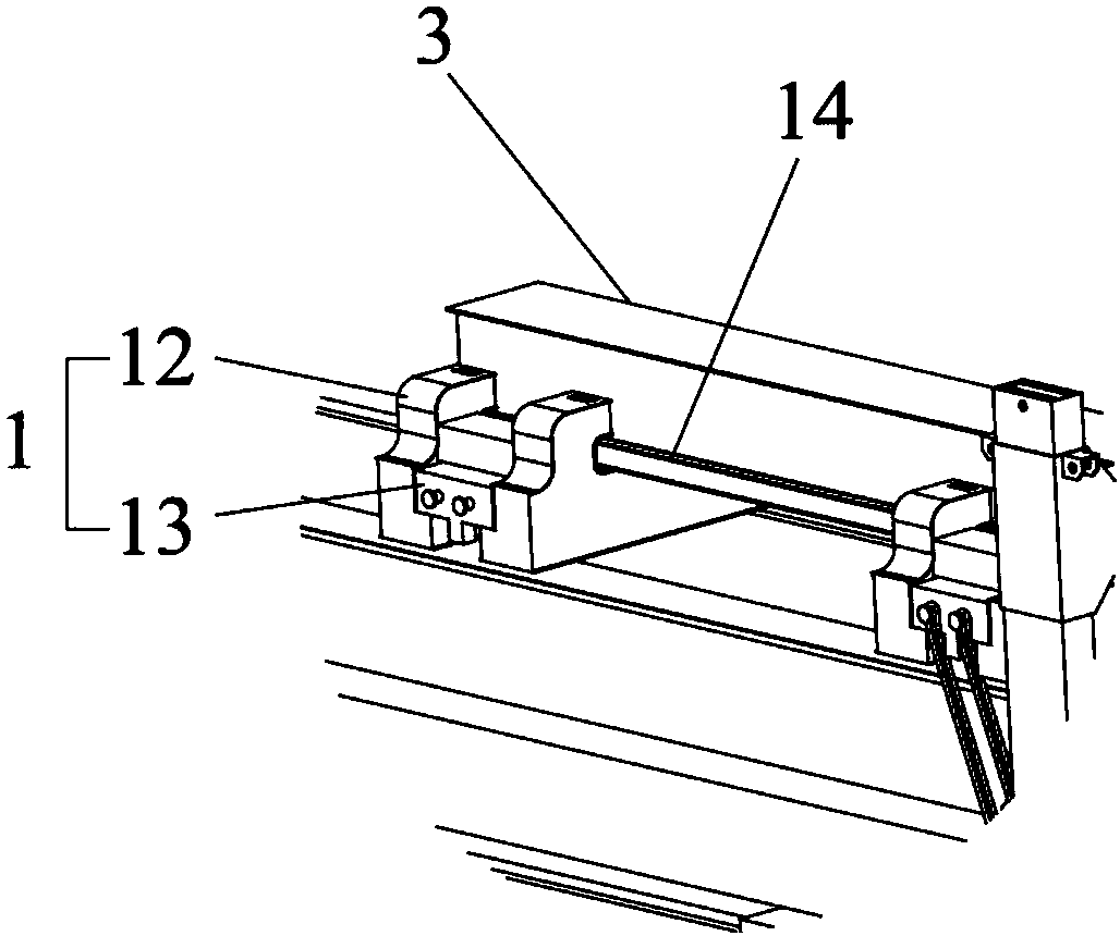
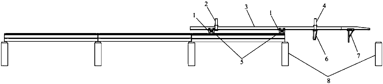
[0023] Combine figure 1 with figure 2 As shown, a girder changing machine for a double T-beam bridge provided by an embodiment of the present invention includes a main girder 3 on which two girder trolleys 1 that can move along its length are provided. 1 is used for hoisting a new beam to be erected; the rear of the main beam 3 i...


PUM


Abstract

The invention relates to technical field of double-T-shaped beam bridge beam-erecting equipment, and provides a bridge erecting machine of a double-T-shaped beam bridge. The bridge erecting machine comprises a main beam, two beam-hoisting trolleys which can move in the length direction of the main beam are arranged on the main beam, and the rear portion of the main beam is erected on a bridge floor through a telescopic rear guiding pillar; a telescopic front guiding pillar is arranged at the front portion of the main beam, the front guiding pillar is erected on a pier at the position with a beam to be erected through a lengthening section at the bottom, and supporting legs which can move in the length direction of the main beam are arranged at the front portion of the main beam; and the beam-hoisting trolleys comprises moving trolley bodies and horizontally-moved transverse crossing beams. According to the bridge erecting machine of the double-T-shaped beam bridge, overall hole passingof the equipment can be completed only through mutual cooperation of the three supporting legs, operating is simple, steps are definite, the hole passing time of the equipment is greatly reduced, andthe hole passing efficiency is improved; and in addition, through the lifting front guiding pillar and the rear guiding pillar, overall lifting of the equipment can be achieved, so that the beam-changing process is not affected by natural conditions such as wind force, error does not occur during beam falling, and the beam changing efficiency is improved.

Description

Technical field [0001] The invention relates to the technical field of double T-beam bridge girder erecting equipment, in particular to a bridge erecting machine for double T-beam bridges. Background technique [0002] For the construction of simply supported girder bridges on newly-built railway lines, there are now many stereotyped bridge erecting machines. With the help of these equipment, the safe and efficient erection of whole-span precast girder can be realized, which greatly increases the speed of bridge construction. However, since the height of the existing bridge erecting machine can reach 8m during the construction operation, which is seriously exceeding the limit, therefore, under the existing line conditions, the existing bridge erecting machine needs to continuously erect the new porous beam after the old beam is removed. Unable to apply, a new type of bridge erecting machine structure must be proposed. Summary of the invention [0003] The purpose of the present i...

Claims


Application Information

Patent Timeline
Patent Type & Authority Applications(China)
IPC IPC(8): E01D21/10
Inventor 蒋中明王治斌王嵽显高占军谢爱华刘均红张俊英李璐
Owner CHINA RAILWAYS CORPORATION
Why Eureka
Try Eureka