Bridging method for T-shaped beam bridge

A bridge erecting machine and girder erection technology, which is applied in the direction of bridges, bridge construction, erection/assembly of bridges, etc., and can solve problems such as inapplicability

Active Publication Date: 2018-01-19
CHINA RAILWAY FIFTH SURVEY & DESIGN INST GRP
View PDF6 Cites 4 Cited by
  • Summary
  • Abstract
  • Description
  • Claims
  • Application Information

AI Technical Summary

Problems solved by technology

However, because the height of the existing bridge erecting machine can reach 8m during construction, which is seriously over the limit, therefore, under the existing line cond

Method used


Image

  • Bridging method for T-shaped beam bridge
  • Bridging method for T-shaped beam bridge
  • Bridging method for T-shaped beam bridge

Examples


Embodiment Construction

[0024] In order to make the purpose, technical solutions and advantages of the embodiments of the present invention clearer, the technical solutions in the embodiments of the present invention will be clearly and completely described below in conjunction with the drawings in the embodiments of the present invention. Obviously, the described embodiments It is a part of embodiments of the present invention, but not all embodiments. Based on the embodiments of the present invention, all other embodiments obtained by persons of ordinary skill in the art without making creative efforts belong to the protection scope of the present invention.

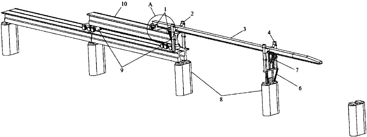
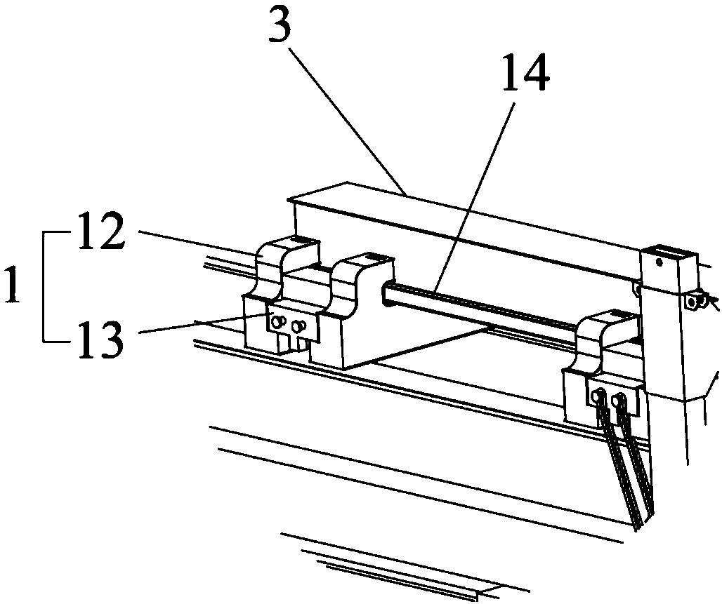
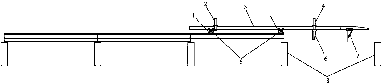
[0025] like figure 1 As shown, a girder exchanging machine for a T-shaped girder bridge provided by an embodiment of the present invention includes a main girder 3, on which two girder trolleys 1 that can move along its length direction are arranged, and the girder trolley 1 Used for hoisting new beams to be erected; the rear of the main bea...


PUM


Abstract

The invention relates to the technical field of T-shaped beam bridge beam-erecting methods, and provides a bridging method for a T-shaped beam bridge. The bridging method comprises the steps that during hole passing, a front guiding pillar and a rear guiding pillar of a bridge erecting machine shrink, and two beam-hoisting trolleys on a main beam are supported on an erected beam bridge deck; the main beam is driven to move forward, so that the front guiding pillar and the rear guiding pillar are moved to the position above two piers at the beam-erecting position correspondingly, and the frontguiding pillar and the rear guiding pillar are stretched downward and supported on the two piers at the beam-erecting position; and during beam erecting, the two beam-hoisting trolleys are matched with a beam transporting trolley for conducting beam feeding, and after a new beam to be erected is transported to the position above the beam-erecting position, the new beam to be erected is erected onthe piers. According to the bridging method for the T-shaped beam bridge, overall hole passing of equipment can be completed only through mutual cooperation of three supporting legs, operation is simple, the hole passing time of the equipment is greatly reduced; and in addition, through the lifting front guiding pillar and the rear guiding pillar, overall lifting of the equipment can be achieved,so that the beam-changing process is not affected by natural conditions such as wind force, and errors do not occur during beam falling.

Description

technical field [0001] The invention relates to the technical field of girder erecting methods for T-shaped girder bridges, in particular to a method for erecting T-shaped girder bridges. Background technique [0002] For the construction of simply-supported girder bridges on new railway lines, there are already many stereotyped bridge erecting machines. With the help of these equipment, the safe and efficient erection of whole-hole prefabricated beams can be realized, which greatly improves the construction speed of bridges. However, because the height of the existing bridge erecting machine can reach 8m during construction, which is seriously over the limit, therefore, under the existing line conditions, the existing bridge erecting machine is convenient for erecting new porous beams after the old beams are removed. If it is not applicable, a new bridging method needs to be proposed. Contents of the invention [0003] The purpose of the present invention is to propose a...

Claims


Application Information

Patent Timeline
IPC IPC(8): E01D21/06E01D2/02
Inventor 王治斌蒋中明王嵽显
Owner CHINA RAILWAY FIFTH SURVEY & DESIGN INST GRP
Why Eureka
Try Eureka