Inflatable water surface take-off and landing parafoil

An inflatable, parafoil technology, applied in the field of parafoils, can solve the problems of small control force and control amount, increased resistance, affecting the intelligence level of the parafoil, etc., and achieve the effect of improving the tensile capacity

Active Publication Date: 2021-04-13
深圳市百川融创科技有限公司
View PDF6 Cites 0 Cited by
  • Summary
  • Abstract
  • Description
  • Claims
  • Application Information

AI Technical Summary

Problems solved by technology

However, both control methods have disadvantages: when the first directional control method is adopted, some unfavorable situations will appear: for example, when one trailing edge is pulled, the lift of the wing surface increases, but the resistance increases faster
In addition, due to the existence of the reverse roll tendency, the control is not flexible enough, and it is easy to cause excessive control and enter the spiral stall motion
Although the second control method is relatively safe, the control force and control amount are relatively small when the method of closing the air inlet of the outer wing is used to control the direction of the large-area throwing parafoil.
And the existing parafoil cannot realize the function of automatic retraction, which has seriously affected the intelligence level of the parafoil
[0004] At the same time, the commonly used ram parafoil has an open air inlet, and the water inlet cannot take off, so it cannot take off on the water surface, which limits its scope of use.

Method used


Image

  • Inflatable water surface take-off and landing parafoil
  • Inflatable water surface take-off and landing parafoil
  • Inflatable water surface take-off and landing parafoil

Examples


Embodiment 1

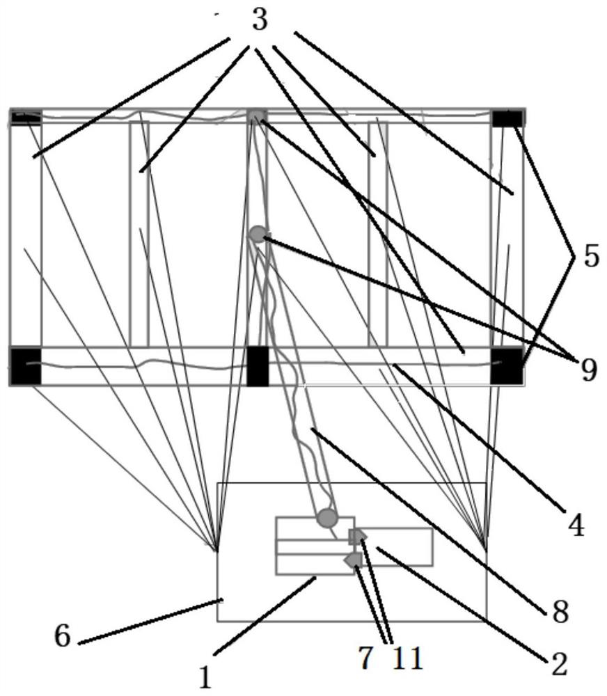
[0043] Such as figure 1 As shown, the present embodiment provides a kind of inflatable water surface take-off and landing parafoil, including: parafoil, inflation and deflation device, retractable device, load compartment 6 and two groups of left and right parafoil ropes ( The load compartment 6 is provided with two parafoil rope fixing bolts 16 for connecting the left and right groups of parafoil ropes respectively). The load compartment 6 has buoyancy and can float on the water surface, so that the parafoil can directly take off and land on the water surface.

[0044]Wherein the parafoil is an inflatable flying parafoil, which has the aerodynamic profile of a flying parafoil after being inflated; direction) of the horizontal inflatable wing umbrella bag and the longitudinal inflatable wing umbrella bag (longitudinal refers to the length direction of the parafoil, which is used to connect a plurality of transverse inflatable wing umbrella bags into a whole) at both ends of t...

Embodiment 2

[0054] On the basis of the above-mentioned embodiment 1, in order to realize the adjustment of the left and right parafoil surfaces through the retracting device, so as to cooperate with the parafoil rope to assist in controlling the steering of the parafoil, two independently controlled The reel, the guide ropes 4 on the left and right sides of the longitudinal direction are respectively wound on two reels, that is, the two guide ropes 4 on the left side are synthesized into one strand in the transverse inflatable wing umbrella bag at the middle position, and then pass through the replacement of the guide device 9. Enter the inflatable parafoil umbilical cord 8 in the direction of traction, and then pass through the inflatable parafoil umbilical cord 8 and wind on one of the drums; The reversing traction of the device 9 enters the inflatable parafoil umbilical cord 8, and then passes through the inflatable parafoil umbilical cord 8 and is wound on another reel; through the ind...

Embodiment 3

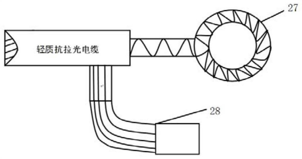
[0056] On the basis of above-mentioned embodiment 1 or embodiment 2, in order to realize the traction of this inflatable water surface take-off and landing parafoil, the load compartment 6 is connected with the traction device 12 (such as winch) that is arranged on the ship through the photoelectric mooring cable 10 , the electrical energy and optical information are transmitted between the control unit on board the ship and the load compartment 6 through the photoelectric mooring cable 10 .

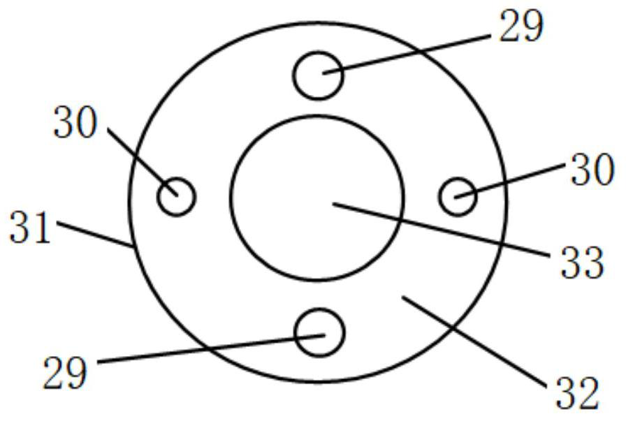
[0057] In addition to its own power and optical information transmission functions, the photoelectric tethered cable 10 also needs to have a certain tensile capacity to carry loads. In order to improve the tensile capacity of photoelectric mooring cable 10, adopt such as figure 2 and image 3 Shown photoelectric mooring cable 10; The structure of the cross section of photoelectric mooring cable 10 is as figure 2 As shown, it includes: an outer sheath 31 and a tensile rope 33 disposed...


PUM


Abstract

The invention discloses an inflatable water surface take-off and landing parafoil which comprises a parafoil body, an inflation and deflation device, a folding and unfolding device, a load cabin, a left parafoil rope and a right parafoil rope, wherein the left parafoil rope and the right parafoil rope are connected with the parafoil body and the load cabin. The load cabin has buoyancy and can float on the water surface, so that the parafoil can take off and land on the water surface. The parafoil comprises three or more transverse inflatable parafoil bags and longitudinal inflatable parafoil bags arranged at the two ends of the transverse inflatable parafoil bags and used for connecting the transverse inflatable parafoil bags into a whole. The inflatable parafoil bags are communicated with one another; the electric inflation / deflation pump inflates / deflates the parafoil through the inflatable parafoil umbilical cord; the two longitudinal ends of the interior of each longitudinal inflatable parafoil bag are each connected with a guide rope, the guide ropes are wound around a winding drum in a sealed cabin of a winder after being subjected to reversing traction of a guide device, and folding and unfolding of the parafoil are achieved through folding and unfolding of the winder on the guide ropes.

Description

technical field [0001] The invention relates to a parafoil, in particular to an inflatable water surface take-off and landing parafoil. Background technique [0002] Traditional marine environment monitoring and detection mostly use on-board monitoring and detection equipment as a parafoil that can make full use of the sea wind for a long time in the air. Compared with on-board monitoring and detection equipment, it can reduce the influence of the curvature of the earth, and the detection distance is longer, and the monitoring efficiency and scope are higher. Wider, more prominent advantages. Based on this, it is necessary to actively explore a parafoil capable of carrying marine environment monitoring and detection equipment. [0003] There are two ways to control the direction of the traditional ram parafoil: the first is to pull down one side of the trailing edge by the control rope; Wings collapsed. But both control methods have deficiencies: when adopting the first c...

Claims


Application Information

Patent Timeline
Patent Type & Authority Applications(China)
IPC IPC(8): B64C31/036B64D47/00B64F3/02B63B35/00B60F5/02
CPCB64C31/036B64D47/00B64F3/02B63B35/00B60F5/02
Inventor 刘松林朱靖
Owner 深圳市百川融创科技有限公司
Why Eureka
Try Eureka