
Electric power warning bar

A security fence and power technology, applied in the direction of fences, building types, buildings, etc., can solve the problems of damage to the cable insulation, crushing of the security fence, difficult to carry, etc., and achieve the effect of strong anti-hook rolling ability.

Inactive Publication Date: 2018-01-19
张若玮
View PDF9 Cites 4 Cited by
  • Summary
  • Abstract
  • Description
  • Claims
  • Application Information

AI Technical Summary

Problems solved by technology

[0003] At present, the electric warning fence is usually carried by the electric work vehicle. During operation, it is taken off from the vehicle and arranged around the electric work site; the electric warning fence is mainly of a fixed type, and it occupies a large space. On a large electric special vehicle It can't carry a few, and it is even more difficult to carry on a small electric emergency repair vehicle; in addition, there are generally warning signs in the electric warning fence, because there is no handle and the space for self-handling is very limited, so when loading and unloading and carrying It is easy to crush your fingers if you are not careful; in addition, the lower part of the electric warning fence is all sharp corners, so that it is easy to be caught by the cable during electric work, and the insulation layer on the surface of the cable will be damaged at the slightest, and the warning fence will be dragged down and crushed Injury to passers-by, damage to property

Method used


Image

  • Electric power warning bar
  • Electric power warning bar

Examples


Embodiment Construction

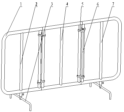
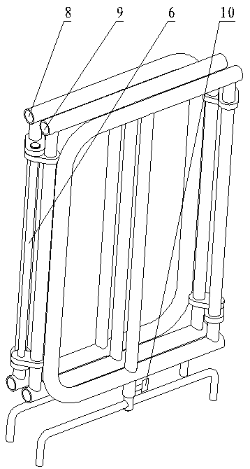
[0019] As shown in the figure, it includes a right side column 2, a middle column 4, and a left side column 7. Between the right side column 2 and the middle column 4, between the middle column 4 and the left side column 7 are hinged to form three Folding guard rail; the upper and lower ends of the right side rail 2 and the left side rail 7 are provided with rounded corners 1, and the upper and lower inner sides of the right side rail 2 and the left side rail 7 are provided with hinge plates 5 in the hinge The bottom of the right column 2 and the left column 7 is provided with a rotary bracket 3; the two sides of the middle column 4 are provided with another hinge plate in the hinge; the hinge plate 5 in the hinge is inserted between the hinge plate and the other hinge plate. Hand 6 forms a hinge part with dual functions of hinge and hand guard, and the hand guard is exposed on both sides of the guardrail after folding.

[0020] The rotary bracket 3 is provided with guide hole...


PUM


Abstract

The invention provides an electric power warning bar. The electric power warning bar integrates three-folding-type and bracket rotating functions. After being folded, handguards are exposed on the twosides of the warning bar, and the electric power warning bar is convenient to carry; after the warning bar is unfolded, round corners are at the periphery of the warning bar, and the hook-and-roll-proof capability is high; and after being folded, according to the width of the warning bar, the warning bar can be carried on any electric operation vehicle. The electric power warning bar is characterized in that the electric power warning bar includes a right side bar, a middle bar and a left side bar, the right side bar and the middle bar are hinged through a hinging part, the middle bar and theleft side bar are hinged through a hinging part, and the three-folding-type warning bar is formed; the round corners are arranged at the upper ends and the lower ends of the outer sides of the rightside bar and the left side bar, hinging plates in the hinging parts are arranged at the upper and lower parts of the inner sides of the right side bar and the left side bar, and rotary brackets are arranged at the lower parts of the right side bar and the left side bar; and another hinging plates in the hinging parts are arranged on the two sides of the middle bar, the handguards are inserted between the hinging plates and the another hinging plates in the hinging parts, and the hinging parts with the hinge and handguard double functions are formed.

Description

technical field [0001] The invention relates to an electric warning fence. Background technique [0002] During electric power work, for the safety of passers-by and vehicles, electric warning fences are generally set up around the power work site to prevent passers-by and vehicles from entering the work site by mistake, affecting the work safety of electric workers and the safety of passers-by themselves. [0003] At present, the electric warning fence is usually carried by the electric work vehicle. During the operation, it is taken off from the vehicle and arranged around the electric work site; the electric warning fence is mainly of a fixed type, and it occupies a large space. On a large electric special vehicle It can't carry a few, and it is even more difficult to carry on a small electric emergency repair vehicle; in addition, there are generally warning signs in the electric warning fence, because there is no handle and the space for self-handling is very limited, s...

Claims


Application Information

Patent Timeline
IPC IPC(8): E04H17/14E04H17/20
Inventor 张若玮
Owner 张若玮
Learn More