Loudspeaker box

A speaker box, back cavity technology, applied in the transducer shell/cabinet/stand, frequency/directional characteristic device, etc., can solve the problems of reducing the volume and affecting the low-frequency acoustic performance of the speaker box, increasing the filling volume, improving the Low frequency performance, simple structure effect

Active Publication Date: 2018-01-19
AAC TECH PTE LTD
View PDF4 Cites 15 Cited by
  • Summary
  • Abstract
  • Description
  • Claims
  • Application Information

AI Technical Summary

Problems solved by technology

The volume of the auxiliary sounding cavity as a virtual acoustic cavity occupied by the setting of the thermal fusion wall and the leaking gap structure reduces the volume of the virtual acoustic cavity, which affects the low-frequency acoustic performance of the speaker box

Method used


Image

  • Loudspeaker box
  • Loudspeaker box
  • Loudspeaker box

Examples


Embodiment Construction

[0021] The present invention will be further described below in conjunction with the accompanying drawings and embodiments.

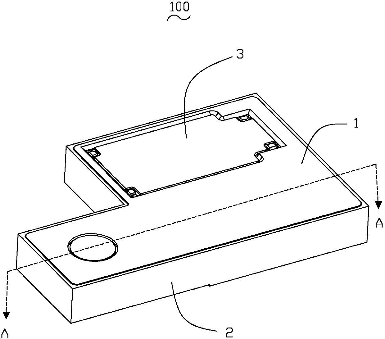
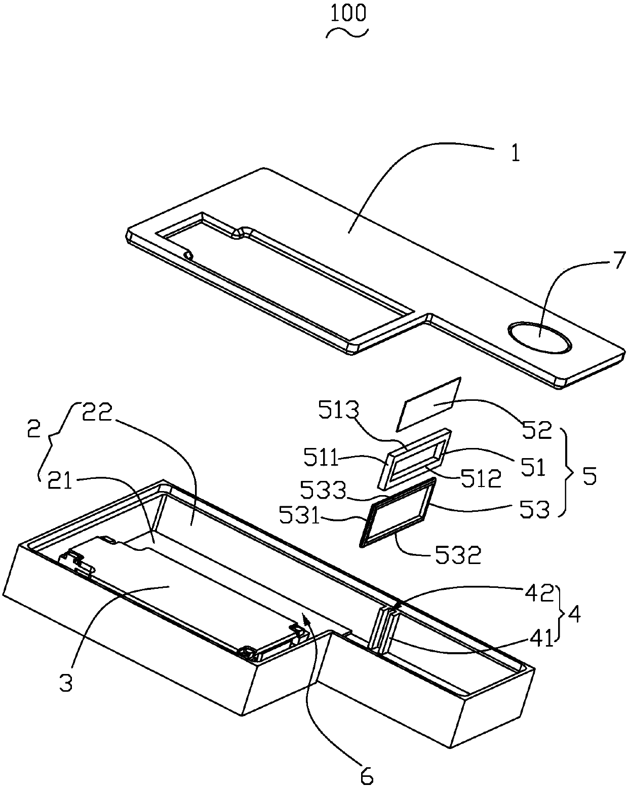
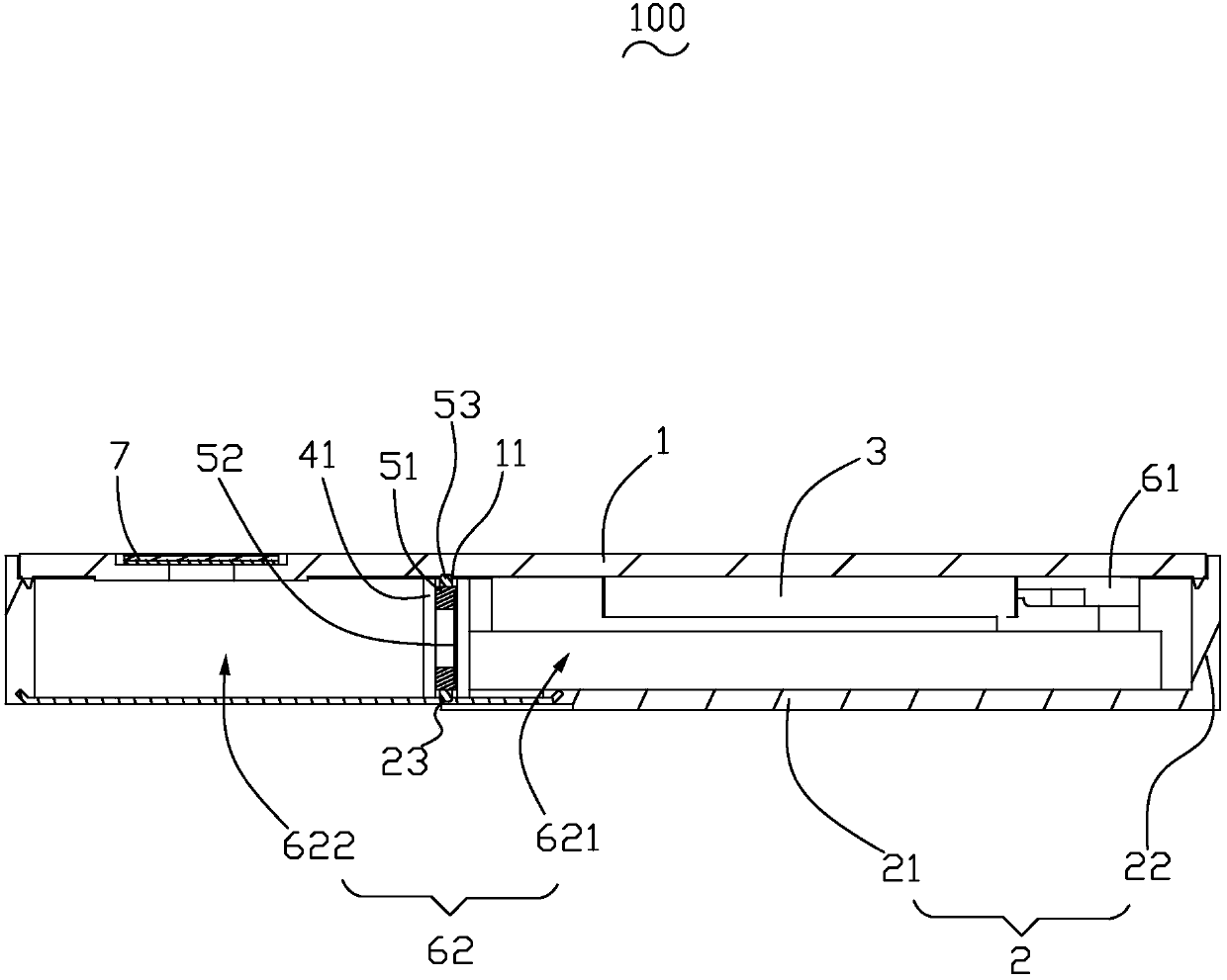
[0022] Please also see Figure 1-3 , the present invention provides a speaker box 100 , including a lower cover 1 , an upper cover 2 , a sounding unit 3 , a clamping wall 4 and a ventilating isolation component 5 . The lower cover 1 and the upper cover 2 are assembled together to form a receiving space 6 . At least one of the lower cover 1 and the upper cover 2 includes a side wall. Specifically, in this embodiment, the lower cover 1 is a plate-shaped structure, and the upper cover 2 includes a bottom wall 21 and a side wall 22. The lower cover 1 is connected to the upper cover. 2 on the side wall 22, thereby forming the accommodation space 6.

[0023] The sounding unit 3 is accommodated in the accommodation space 6, and the sounding unit 3 and the upper cover 2 form a front cavity 61; the sounding unit 3, the lower cover 1 and the upper cover 2 toget...


PUM


Abstract

The invention discloses a loudspeaker box comprising a lower cover, an upper cover and a sound generating monomer. The sound generating monomer and the upper cover form a front cavity through enclosing. The sound generating monomer, the lower cover and the upper cover form a rear cavity together through enclosing. The loudspeaker box also comprises a ventilating isolation component and clamp walls. The ventilating isolation component is fixedly clamped between the clamp walls, and the ventilating isolation component and the clamp walls divide the rear cavity into a first rear cavity and a second rear cavity which are mutually communicated together. The sound generating monomer is arranged in the first rear cavity. The second rear cavity is filled with sound absorbing particles. The ventilating isolation component packages the sound absorbing particles in the second rear cavity. The ventilating isolation component comprises a framework, screen cloth which is combined on the framework and elastomers which are arranged at the periphery of the framework. The elastomers are inserted in the clamp walls. The upper cover, the lower cover and the clamp walls extrude the elastomers to form sealing. Compared with the loudspeaker boxes in the prior art, the loudspeaker box has better low frequency acoustic performance and great sealing performance.

Description

【Technical field】 [0001] The invention relates to an electroacoustic device, in particular to a speaker box. 【Background technique】 [0002] With the advent of the mobile Internet era, the number of smart mobile devices continues to rise. Among the many mobile devices, the mobile phone is undoubtedly the most common and portable mobile terminal device. At present, the functions of mobile phones are extremely diverse, one of which is the function of high-quality music. Therefore, speaker boxes for playing sound are widely used in current smart mobile devices. [0003] The speaker box in the related art includes a lower cover, an upper cover that is combined with the lower cover to form a storage space, a sounding unit accommodated in the storage space, and a baffle extending from the upper cover to the lower cover. wall, the sounding unit and the upper cover form a front cavity, the sounding unit, the upper cover and the lower cover together form a rear cavity, and the reta...

Claims


Application Information

Patent Timeline
Patent Type & Authority Applications(China)
IPC IPC(8): H04R1/02H04R1/22
Inventor 黄兴志施胜荣蔡斌柳林王程良
Owner AAC TECH PTE LTD
Why Eureka
Try Eureka