

Antenna structure
An antenna structure and antenna technology, applied in the field of antenna structures and antennas, can solve problems such as poor low-frequency performance, thick terminals, and poor user experience, and achieve the effects of expanding the antenna routing area, reducing the height of the bracket, and improving low-frequency performance
- Summary
- Abstract
- Description
- Claims
- Application Information
AI Technical Summary
Problems solved by technology
Method used
Image

Examples
Embodiment Construction
[0032] The present invention will be further described in detail below in conjunction with the accompanying drawings and specific embodiments.
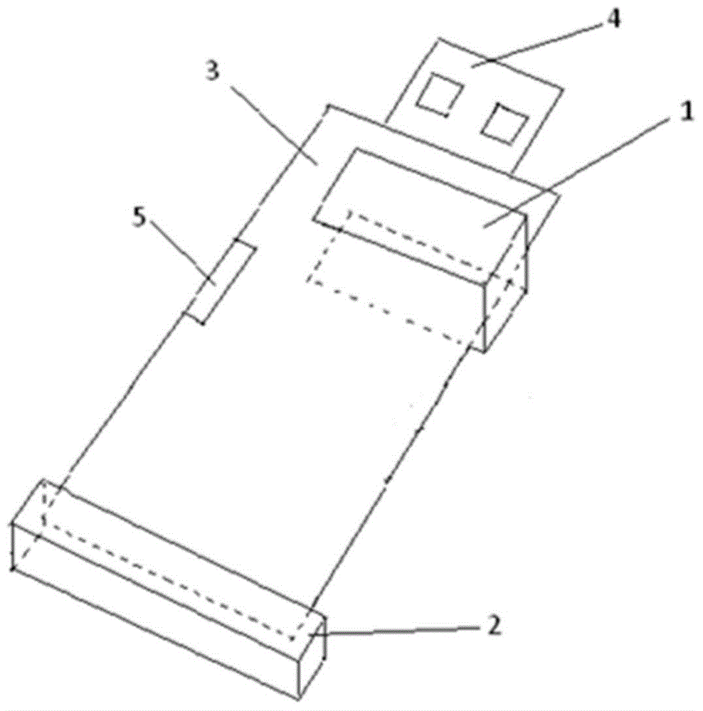
[0033] figure 1 is a schematic diagram of the antenna structure of a data card terminal, such as figure 1 As shown, the diversity antenna 1 is close to the USB head 4 of the data card, the main antenna 2 is far away from the USB head of the data card, and the Wifi antenna 5 is located on the left side of the main board 3; wherein, the main antenna 2 and the diversity antenna 1 both adopt the traditional Single-sided bracket form.
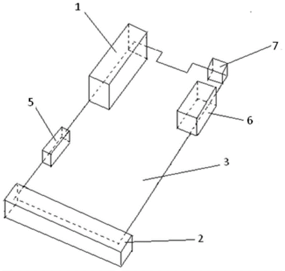
[0034] figure 2 It is a schematic diagram of the antenna structure of a mobile phone terminal. Such as figure 2 As shown, the antenna structure includes a diversity antenna 1 , a main antenna 2 , a Wifi antenna 5 , a GPS positioning antenna 6 , and a Bluetooth antenna 7 . Since the antenna structure of the mobile phone terminal mainly considers the space of the main antenna 2, the diversity antenna 1...
PUM
 Abstract
Description
Claims
Application Information