
Gear arrangement

A technology for configuring components and gears, which is applied to transmission parts, components with teeth, belts/chains/gears, etc., can solve problems such as disturbing noise, improve tooth wear, reduce noise generation, and simplify manufacturing Effect

Inactive Publication Date: 2018-01-26
MIBA SINTER AUSTRIA
View PDF15 Cites 0 Cited by
  • Summary
  • Abstract
  • Description
  • Claims
  • Application Information

AI Technical Summary

Problems solved by technology

[0005] In operation of such gear arrangements it has been shown that these gear arrangements may generate disturbing noises

Method used


Image

  • Gear arrangement
  • Gear arrangement
  • Gear arrangement

Examples


Embodiment Construction

[0017] As an introduction, it should first be stated that in the various embodiments described differently, the same reference numerals or the same component names are assigned to the same components, wherein the disclosure content contained in the entire description can be used according to the meaning to the same part provided with the same reference number or the same component name. Furthermore, the orientation instructions selected in the specification, such as up, down, sideways, etc., are relative to the direct description and shown drawings, and when the orientation changes, they can be transferred to the new orientation according to the meaning.

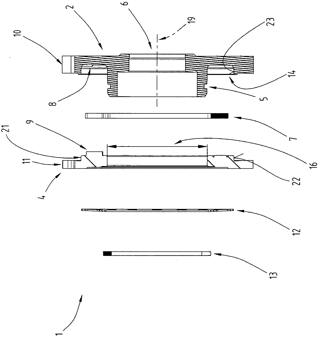
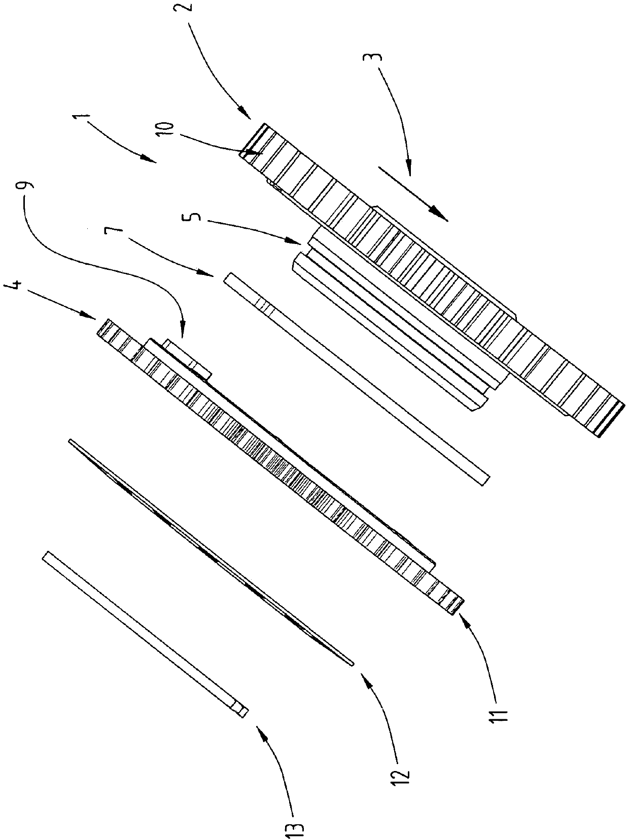
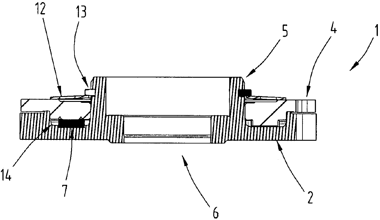
[0018] Figures 1 to 3 Shown is an exploded or cross-sectional view of the gear arrangement 1 . This gear arrangement 1, also referred to as a "split gear", has a main gear 2 and a gear 4 which is oppositely rotatable in the circumferential direction 3, wherein the main gear 2 has a hub 5 which In particular, it is integra...


PUM


Abstract

The invention relates to a gear arrangement (1) with a divided spur toothing, comprising a main gear (2) and a gear (4) rotatable to the latter in circumferential direction (3), wherein the main gear(2) has a hub (5) on which the rotatable gear (4) is arranged and comprising a spring element (7), which is arranged between the main gear (2) and the rotatable gear (4), and with which the rotatablegear (4) is pretensioned in circumferential direction (3) against the main gear (2), wherein a first spur toothing part (10) of the spur toothing is formed on the main gear (2) and a second spur toothing part (11) of the spur toothing is formed on the rotatable gear (4), and the first spur toothing part (10) has a first axis of rotation (19) and the second spur toothing part (11) has a second axisof rotation (18). The second axis of rotation (18) of the second spur toothing part (11) is offset relative to the first axis of rotation (19) of the first spur toothing part (10).

Description

technical field [0001] The present invention relates to a gear configuration assembly, which comprises: a split-type cylindrical tooth part; a main gear and a gear that is rotatable in the circumferential direction relative to the main gear, wherein the main gear has a hub, and the rotatable gear is arranged on the On the hub; and an elastic element, the elastic element is arranged between the main gear and the said twistable gear, and through the elastic element, the twistable gear is preloaded relative to the main gear along the circumferential direction, wherein, on the main gear A first cylindrical toothing of the cylindrical toothing and a second cylindrical toothing of the cylindrical toothing are formed on the rotatable gear, and the first cylindrical toothing has a first axis of rotation and the second cylindrical toothing The tooth has a second axis of rotation. Background technique [0002] Such gear arrangements for eliminating backlash between intermeshing gears...

Claims


Application Information

Patent Timeline
IPC IPC(8): F16H55/17F16H55/12
CPCF16H55/14F16H55/18F16H57/12F16H55/17F16H57/0006F16H55/566
Inventor M·施泰因毛雷尔M·海斯曼W·西斯尔K·迪金格尔
Owner MIBA SINTER AUSTRIA
Learn More