A supersonic mandibular air intake front plug

An air intake and supersonic technology, applied in the field of ramjet engines, can solve problems such as high cost, dangerous aircraft platform, and air intake surge, and achieve the effects of low research and development costs and improved reliability and safety

Active Publication Date: 2019-06-28
JIANGXI HONGDU AVIATION IND GRP
View PDF4 Cites 0 Cited by
  • Summary
  • Abstract
  • Description
  • Claims
  • Application Information

AI Technical Summary

Problems solved by technology

Since the rear end of the intake port is connected to the afterburning chamber of the ramjet engine, the rear end of the intake port is blocked at this time. Once the high-speed air passes through figure 1 The entry of the air intake lip 3 into the air intake cavity 2 will cause complex reactions such as air intake surge, resulting in unstable flight of the ramjet aircraft. At the same time, the front end cover of the air intake needs to ensure fast and reliable opening
[0003] At present, the main structural forms of the mainstream supersonic inlet front plug at home and abroad are the integral throwable type and the explosive fragile type. When the integral throwable front cover falls off from the aircraft, it may hit the carrier platform and threaten the safety of the carrier platform.
The explosion-fragile type is to blast the front plug into fine ablative particles in the form of pyrotechnic explosion when the ramjet engine is transferred. However, because the development cost of the fragile plug is quite high, the development cost is often as high Millions, the cost is very high

Method used


Image

  • A supersonic mandibular air intake front plug
  • A supersonic mandibular air intake front plug
  • A supersonic mandibular air intake front plug

Examples


Embodiment Construction

[0018] Below in conjunction with accompanying drawing and embodiment the present invention will be further described:

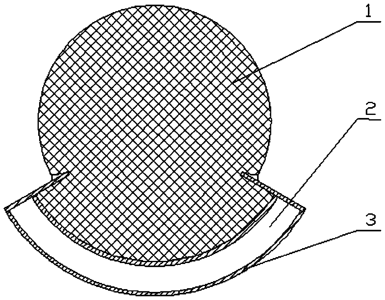
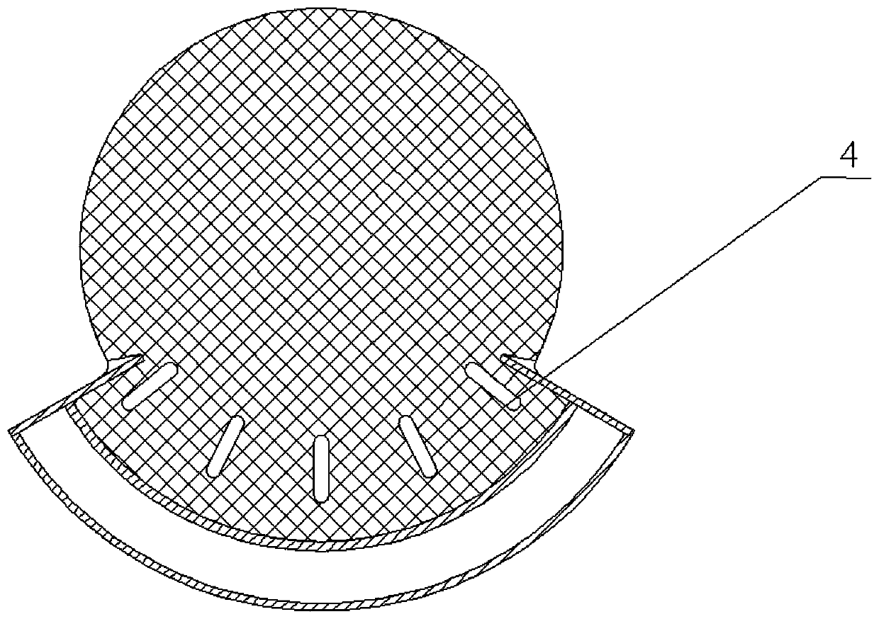
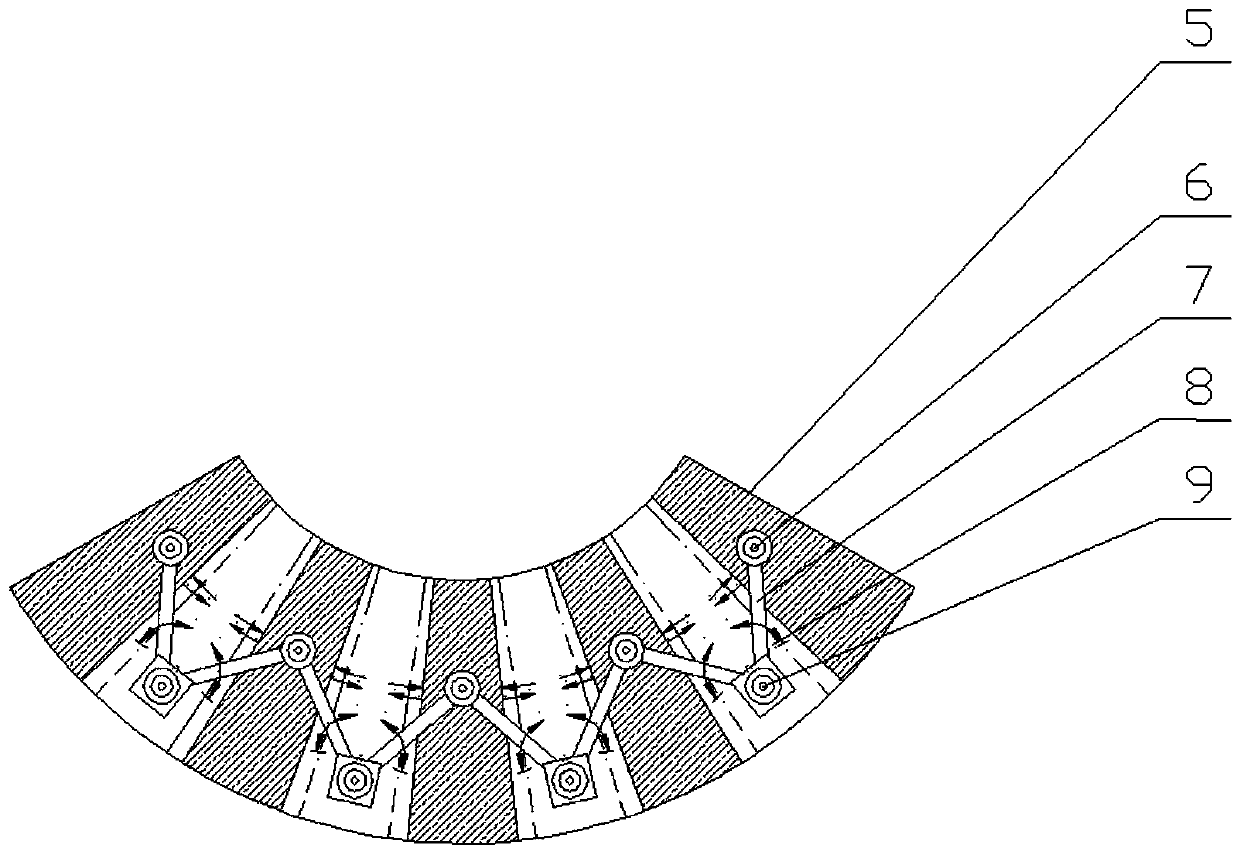
[0019] Please also see figure 2 , the supersonic mandibular air intake front plug of the present invention is installed on the aircraft head 1 and the air intake lip 3, and is used to close and open the air intake cavity 2, which includes a plurality of first regulating pieces 5, sliding pins 6 , connecting rod 7, some second adjusting pieces 8 and fixed pin 9. Wherein the first adjusting piece 5 and the second adjusting piece 8 are interlaced with each other, and all the first adjusting pieces 5 are on the same plane, and all the second adjusting pieces 8 are on another same plane, the first adjusting piece There is a height difference between the planes where the 5 and the second regulating piece 8 are located so as to be staggered from each other. In addition, the first adjusting piece 5 and the second adjusting piece 8 have the same width, so as to red...


PUM


Abstract

The invention belongs to the scramjet technology and particularly relates to a supersonic lower jaw air intake duct front blocking cap. The supersonic lower jaw air intake duct front blocking cap is mounted on the head (1) and an air intake duct lip (3) of an aircraft and used for closing and opening an air intake duct cavity (2). The supersonic lower jaw air intake duct front blocking cap comprises a plurality of first adjustment sheets (5), sliding pins (6), connecting rods (7), a plurality of second adjustment sheets (8) and fixing pins (9), wherein the first adjustment sheets (5) and the second adjustment sheets (8) are arranged in an alternately spaced mode; the fixing pins (9) and the sliding pins (6) are arranged on the first adjustment sheets (5) and the second adjustment sheets (8) correspondingly; the sliding pins (6) on the adjacent adjustment sheets are movably connected with the fixing pins (9) through the connecting rods (7); the sliding pins (6) are arranged in sliding grooves of the head (1) of the aircraft and can slide freely in the sliding grooves (4). By using the supersonic lower jaw air intake duct front blocking cap, the problem that an integrated jettisonable front blocking cap threatens an aircraft carrying platform is avoided; meanwhile, the research and development cost can be minimized; the supersonic lower jaw air intake duct front blocking cap canbe repeated used at the research and development stage; and the reliability and safety are improved.

Description

technical field [0001] The invention belongs to the technology of ramjet, and in particular relates to a front blocking cover of a supersonic mandibular air inlet. Background technique [0002] The front plug of the supersonic air inlet is to prevent high-speed air from entering the air inlet when the integral solid rocket ramjet works in the boosting stage. Since the rear end of the intake port is connected to the afterburning chamber of the ramjet engine, the rear end of the intake port is blocked at this time, once the high-speed air passes through figure 1 The entry of the air intake lip 3 into the air intake cavity 2 will cause complex reactions such as air intake surge, resulting in unstable flight of the ramjet aircraft. At the same time, the front end cover of the air intake needs to ensure It can be opened quickly and reliably. [0003] At present, the main structural forms of the mainstream supersonic inlet front plug at home and abroad are the integral throwable...

Claims


Application Information

Patent Timeline
Patent Type & Authority Patents(China)
IPC IPC(8): F02C7/057
CPCF02C7/057
Inventor 余文锋赵胜海张林卢杰袁晓昱邓波江海涛孙子杰马少杰王啸雄王利林景晓磊
Owner JIANGXI HONGDU AVIATION IND GRP
Why Eureka
Try Eureka