Semi-physical simulation testing table of network control system of high-speed motor train unit train

A technology of train network control and semi-physical simulation, which is applied in the direction of railway vehicle testing, etc., can solve problems such as environments that do not have debugging and verification, and achieve the effects of shortening the development cycle, reducing research and development costs, and shortening the debugging time on the train

Inactive Publication Date: 2011-08-17
CRRC QINGDAO SIFANG ROLLING STOCK RES INST
View PDF5 Cites 28 Cited by
  • Summary
  • Abstract
  • Description
  • Claims
  • Application Information

AI Technical Summary

Problems solved by technology

However, the design process of the TCMS system is often parallel to the design process of the train, so the environment for

Method used


Image

  • Semi-physical simulation testing table of network control system of high-speed motor train unit train
  • Semi-physical simulation testing table of network control system of high-speed motor train unit train
  • Semi-physical simulation testing table of network control system of high-speed motor train unit train

Examples


specific Embodiment approach

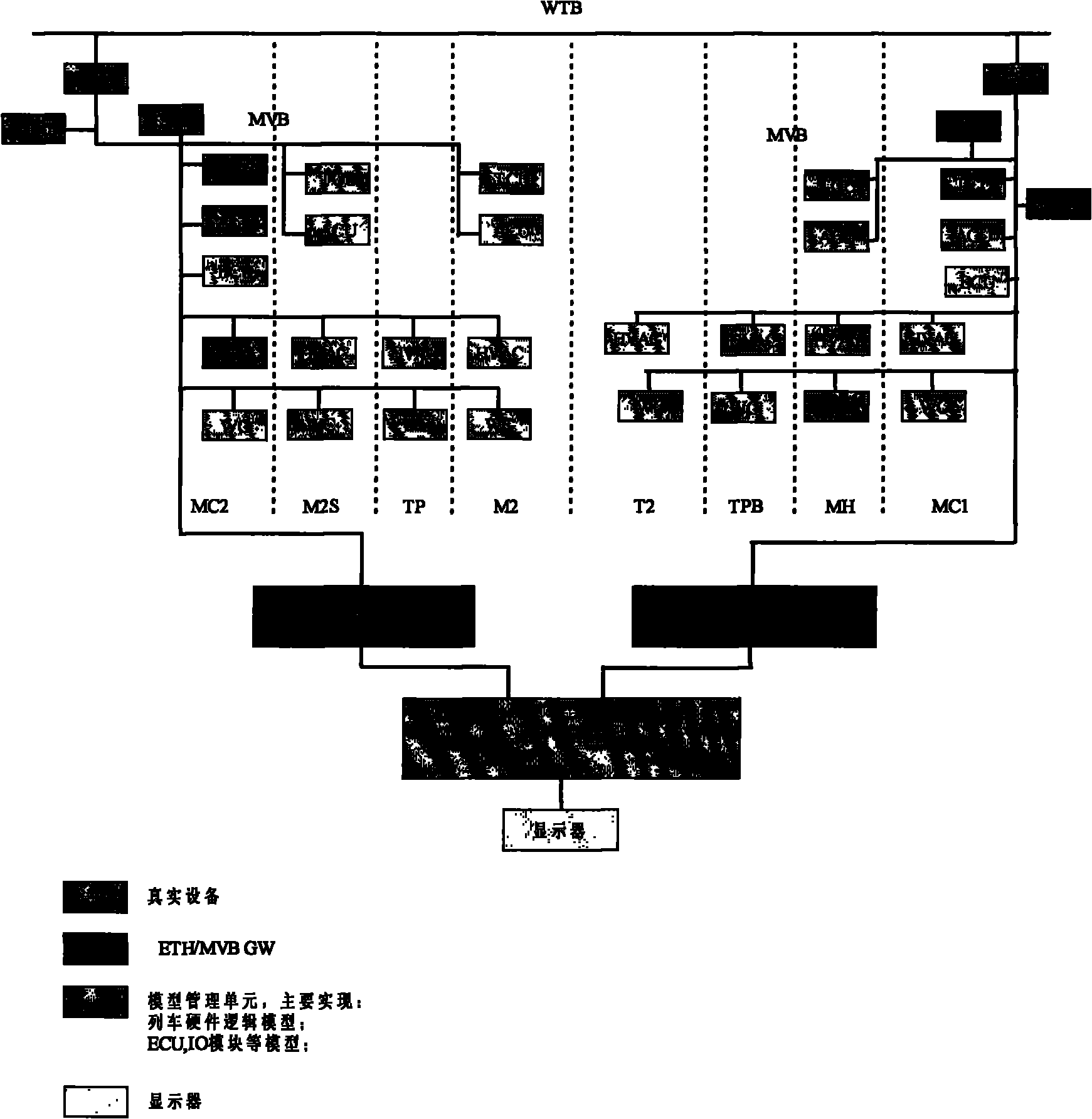
[0012] A kind of high-speed EMU train network control system semi-physical simulation test-bed, described semi-physical simulation test-bed comprises model management unit, real equipment and model unit communicating with model management unit; Wherein, real equipment comprises train central control unit ( CCU), gateway (GW), display screen (MMI), traction control unit (DCU), auxiliary control unit (ACU), air conditioning controller (HVAC) and passenger information system (PIDS); model units include traction control unit (DCU ), Auxiliary Control Unit (ACU), Brake Control Unit (ECU), Air Conditioning Controller (HVAC) and Toilet Controller (WC); the above-mentioned real equipment and model units communicate with the model through the MVB network bus and through the Ethernet / MVB gateway Snap-in communication. The model management unit is provided with a display. In the real equipment, there is one traction control unit (DCU), one auxiliary control unit (ACU), and one air-condi...


PUM


Abstract

The invention relates to a semi-physical simulation testing table of a network control system of a high-speed motor train unit train. The semi-physical simulation testing table comprises a model management unit, a real device and a model unit, wherein the real device and the model unit communicate with the model management unit. The semi-physical simulation testing table has the following obvious advantages in train control algorithm and control logic verification and optimization: lowering the research and development cost: by the establishment of the semi-physical simulation testing table of a high-speed trainset control and management system (TCMS), the research and development period is shortened, the research and development cost is lowered; shortening the development and manufacturing period: the establishment of the semi-physical simulation testing table of the high-speed TCMS contributes to the shortening of the debugging time on the train.

Description


Claims


Application Information

Patent Timeline
Owner CRRC QINGDAO SIFANG ROLLING STOCK RES INST
Why Eureka
Try Eureka