Electrical connector for circuit boards and electrical connector assembly for circuit boards

A technology of circuit substrates and electrical connectors, which is applied to the components, circuits, and connections of connection devices, which can solve the problems of low height and insufficient realization of connectors, and achieve the effect of low height

Active Publication Date: 2018-03-16
HIROSE ELECTRIC GROUP
View PDF1 Cites 5 Cited by
  • Summary
  • Abstract
  • Description
  • Claims
  • Application Information

AI Technical Summary

Problems solved by technology

[0006] However, in the case of the above-mentioned Patent Document 1, among the plurality of connected bodies forming the connector, the terminal protrudes long from the movable holding body toward the counterpart connector, and a contact portion is provided at the front end thereof, so that the terminal is connected to the counterpart connector. The contact pressure is ensured by flexing laterally when the terminals are in contact, but the height of the connector cannot be sufficiently reduced because the terminals protrude long from the movable holder

Method used


Image

  • Electrical connector for circuit boards and electrical connector assembly for circuit boards
  • Electrical connector for circuit boards and electrical connector assembly for circuit boards
  • Electrical connector for circuit boards and electrical connector assembly for circuit boards

Examples


Embodiment Construction

[0024] Embodiments of the present invention will be described below based on the drawings.

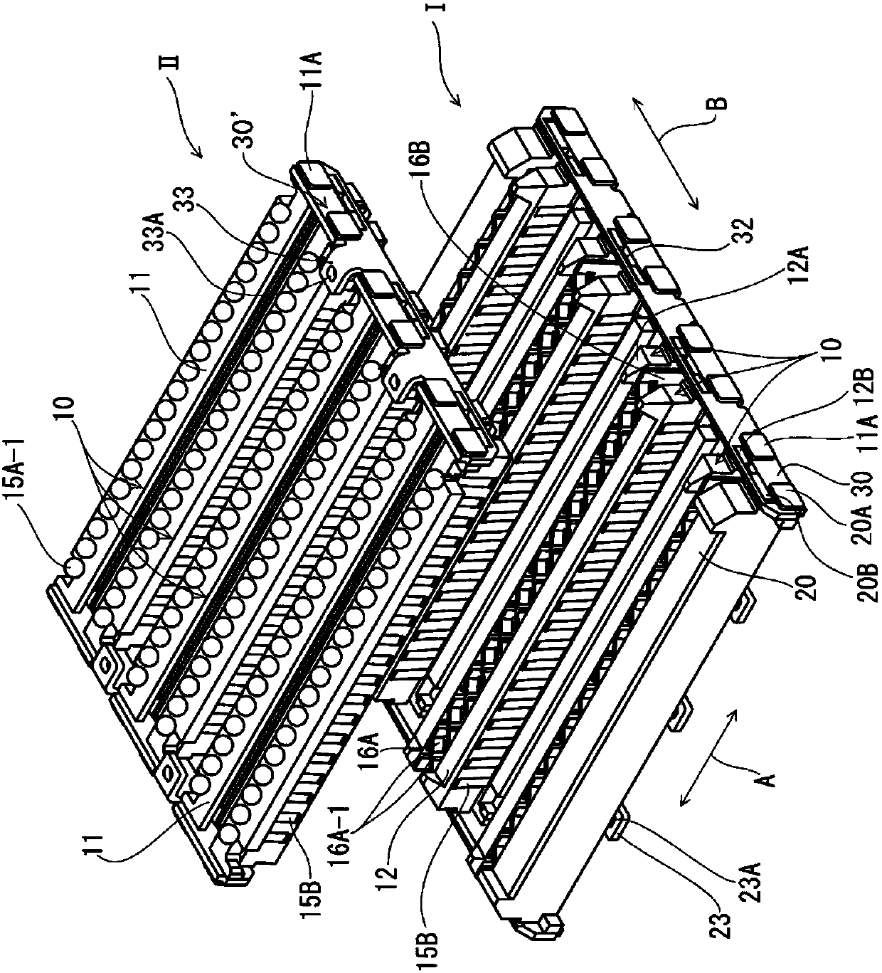
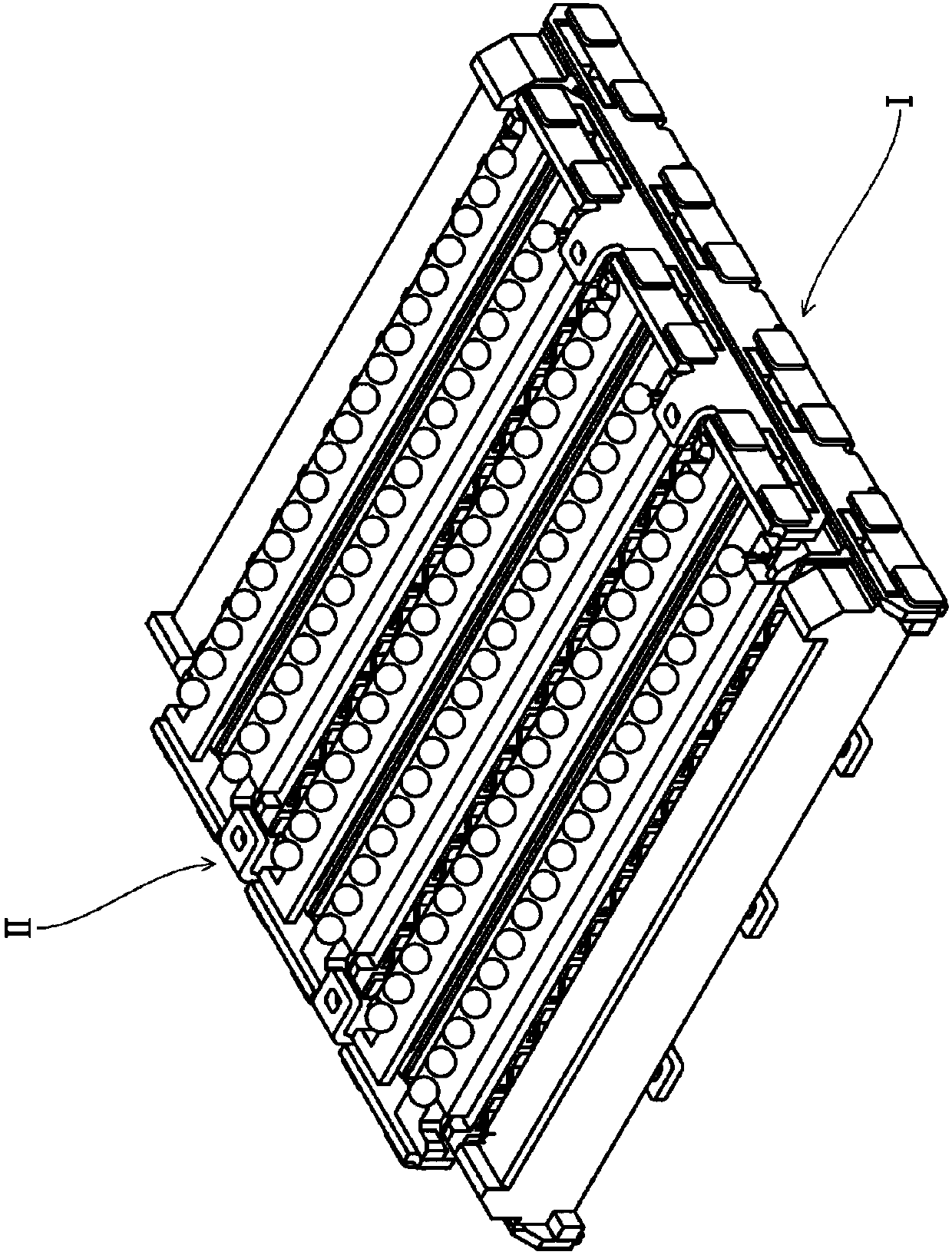
[0025] figure 1 as well as figure 2 It is a perspective view showing an electrical connector I for a circuit board (hereinafter referred to as "connector I") and a corresponding connector II (hereinafter referred to as "connector II") of the present embodiment, figure 1 Indicates before the chimeric connection of two connectors I and II, figure 2 Indicates after chimeric join. For the opposite connector II, the same reference numerals are assigned to the same elements as those of the connector I, and the above-mentioned common elements of the two connectors I, II are in figure 1 In the perspective view of , only one of the connector I or the connector II can be seen, so the common elements will be described with reference to the two connectors I and II.

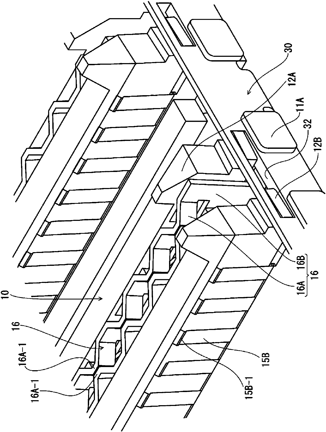
[0026] Connectors I and II respectively have a plurality of connectors 10, and figure 1 In the examples shown, each has six l...


PUM


Abstract

The invention provides an electrical connector for circuit boards and an electrical connector assembly for circuit boards. Floating and low advancement can be achieved. The connector has multiple connection elements arranged on a circuit board and supports which support the connection elements. The connection elements have terminals connected to counterpart terminals in a counterpart connector, aswell as stationary retainers and movable retainers that secure the terminals in place. The terminals have connecting portions at one end of the terminals, and contact portions at the other end, and the contact portions are secured in place on one side of the movable retainers. Flexible portions are formed between the movable retainers and the stationary retainers. The movable retainers are provided with biasing members on the other side opposite to the side on which the contact portions are positioned. A force application part applies force to push other adjacent connectors when being connected with a target connector, so by use of the counter-acting force, the contact part is in contact with a target terminal of the target connector with the contact pressure.

Description

technical field [0001] The present invention relates to an electrical connector for a circuit board and an electrical connector assembly for a circuit board. Background technique [0002] Regarding the electrical connector for circuit boards (hereinafter referred to as "connector"), a so-called "connector" that allows the terminals to have flexibility in a direction parallel to the mounting surface of the circuit board to which the connector is mounted has been proposed. A floating type connector is disclosed in Patent Document 1, for example. [0003] In the case of the connector of Patent Document 1, a connection portion is provided at one end in the longitudinal direction of the terminal extending in a direction perpendicular to the mounting surface, a contact portion is provided at the other end, and between the connection portion and the contact portion, One connecting body is formed by holding terminals at a position closer to the connecting portion by a fixed holder ...

Claims


Application Information

Patent Timeline
Patent Type & Authority Applications(China)
IPC IPC(8): H01R12/71H01R13/02H01R13/502H01R13/627
CPCH01R12/716H01R13/02H01R13/502H01R13/6275H01R12/712H01R12/73H01R12/91H01R13/193H01R13/28H01R13/6315
Inventor 玉井畅洋
Owner HIROSE ELECTRIC GROUP
Why Eureka
Try Eureka