A key switch device using ultra-thin and ultra-small metal scissor feet
A scissor foot, key switch technology, applied in the direction of electrical switches, electrical components, contact operating parts, etc., to achieve compact structure, thin thickness, good elasticity
- Summary
- Abstract
- Description
- Claims
- Application Information
AI Technical Summary
Problems solved by technology
Method used
Image
Examples
Embodiment 1
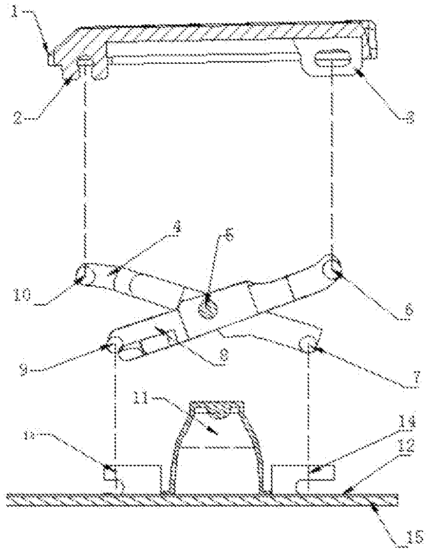
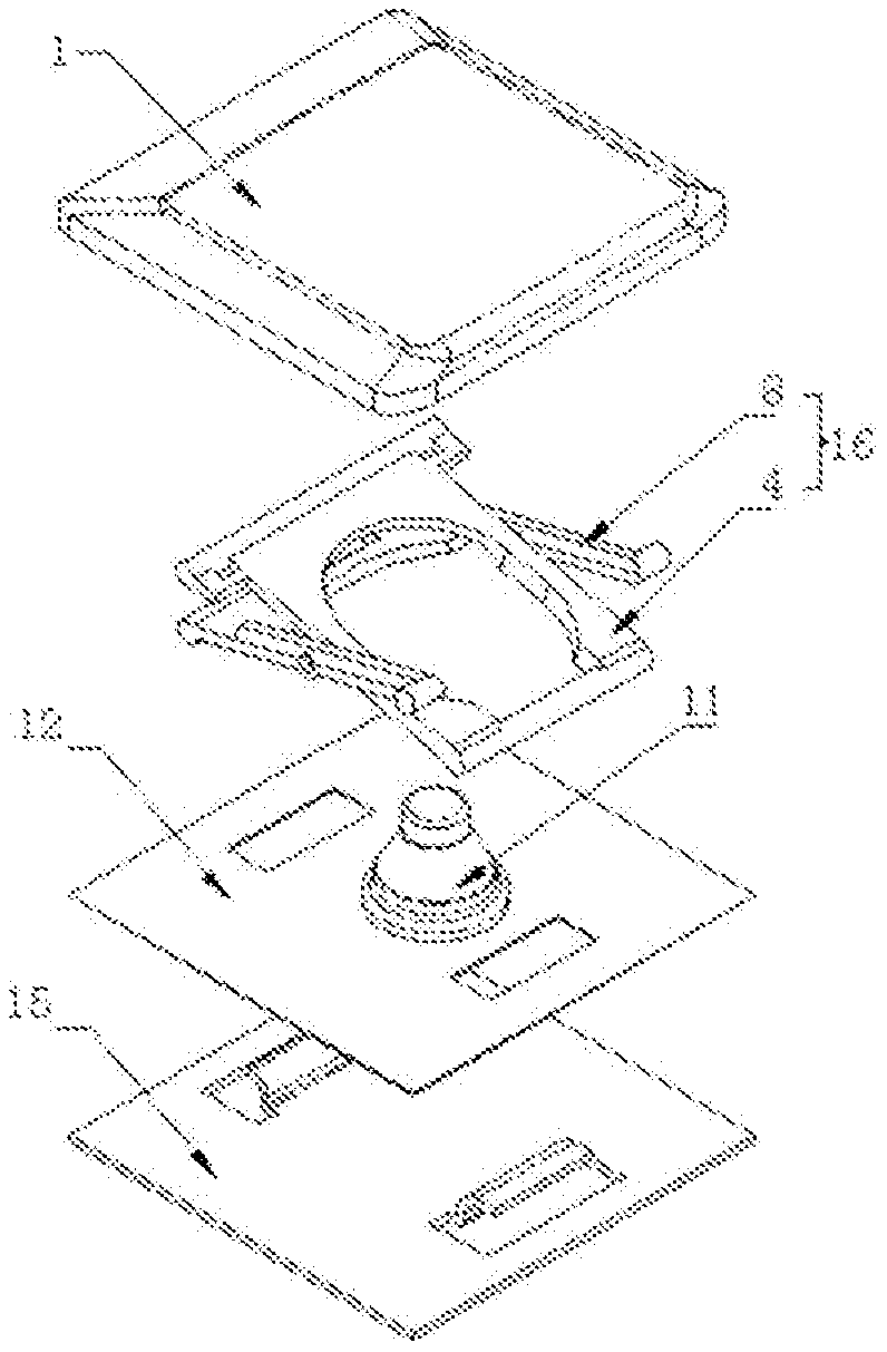
[0136] like Figure 10 , Figure 15 , Figure 16 As shown, the present invention comprises a key cap (not shown in the figure), a reset element 11, a switch circuit 12 with a switch, a support plate 15 with a matching portion, and a scissor foot 16 with an upper and lower matching portion, and the scissors foot 16 passes through the upper and lower matching portion Connect with the mating portion of keycap 1 and support plate 15 respectively, wherein the lower plate surface of the scissors upper plane 19 of one scissors foot 16 and the end of the scissors lower plane 17 of the other scissors foot 16 support each other to form mutual force The transmission constitutes a synchronous linkage support structure to ensure that the keycap is parallel to the support plate for lifting movement. The reset element in this embodiment is an elastic rubber elastic ring (the existing reset element can be a spring, a magnetic element, etc.). An example of a switch circuit with switches is a...
Embodiment 2
[0155] see Figure 17a -- Figure 26 1. The metal scissors feet are stamped and formed on the metal plate surface; the metal scissors feet are formed with an elastic sheet metal elastic plate surface 20; the metal scissors feet have a stamped and formed scissors anti-off structure; the key cap 1 is provided with a key limit protrusion Platform 48; the metal scissors feet supporting each other cooperate with the key limiting boss 48 of the key cap 1 through the scissors anti-off structure, so as to prevent the key from coming out or limit the key cap 1 to the upper limit position.
[0156] The upper mating part of the metal scissors foot 16 is composed of the lower plate surface of the upper end of the scissors, the upper plate surface of the upper end of the scissors, and the independently provided anti-off structure of the scissors. The undercut cambered surface 46 cooperates.
[0157] see Figure 17a 1. Rigid key-limiting bosses 48 are respectively provided near the middl...
Embodiment 3
[0174] see Figure 27 , Figure 28 1. The cantilever notch through hole 20a near the middle of the upper end of the metal scissors legs divides the upper part of the metal scissors legs into left and right parts. There is an upwardly extending plate surface at the bottom of the lower end of the cantilever notch through hole 20a. The upwardly extending plate surface constitutes the sheet metal elastic The plate surface 20, the sheet metal elastic plate surface 20 is located in the middle of the upper part of the metal scissors feet.
[0175] (not shown in this scheme figure), it is also possible to widen the plate surface extending upwards, narrow the plate surface of the metal scissors feet on the left and right sides of the cantilever notch through hole 20a, and make the left side of the cantilever notch through hole 20a and the metal scissors feet on the right side have elasticity, the metal scissors feet on the left side and the right side of the cantilever notch through h...
PUM
 Abstract
Description
Claims
Application Information
 - R&D
- Intellectual Property
- Life Sciences
- Materials
- Tech Scout
- Unparalleled Data Quality
- Higher Quality Content
- 60% Fewer Hallucinations
Browse by: Latest US Patents, China's latest patents, Technical Efficacy Thesaurus, Application Domain, Technology Topic, Popular Technical Reports.
© 2025 PatSnap. All rights reserved.Legal|Privacy policy|Modern Slavery Act Transparency Statement|Sitemap|About US| Contact US: help@patsnap.com


