coaxial connector

A coaxial connector and electrical connection technology, which is applied in the direction of connection, two-part connection device, and parts of the connection device, etc., can solve the problem of limited low height of coaxial connectors, and achieve the effect of low height

Inactive Publication Date: 2015-08-19
FUJIKURA LTD
View PDF6 Cites 0 Cited by
  • Summary
  • Abstract
  • Description
  • Claims
  • Application Information

AI Technical Summary

Problems solved by technology

Therefore, since the overall height of the insulator including the middle cover depends on the diameter of the coaxial cable, the reduction in height of the coaxial connector is limited.

Method used


Image

  • coaxial connector
  • coaxial connector
  • coaxial connector

Examples


Embodiment Construction

[0023] Hereinafter, an embodiment of the present invention will be described based on the drawings.

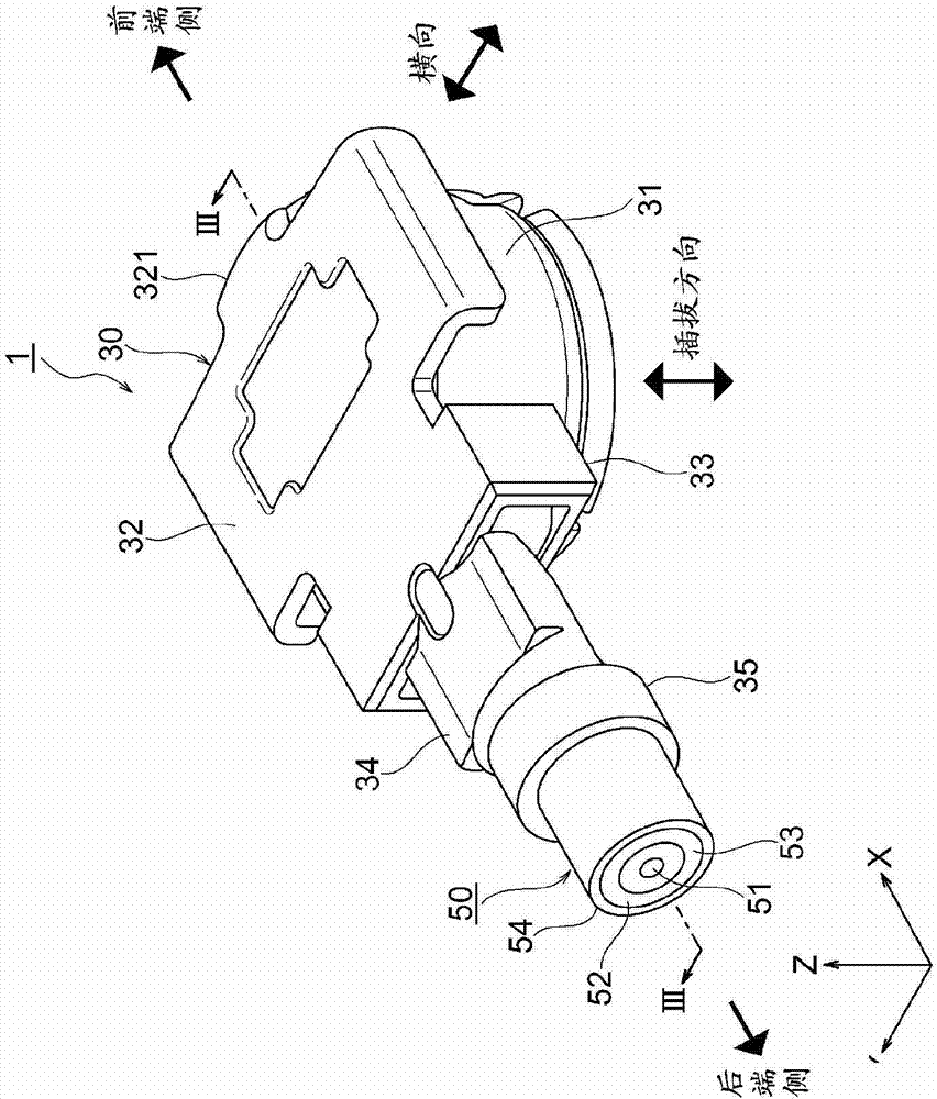
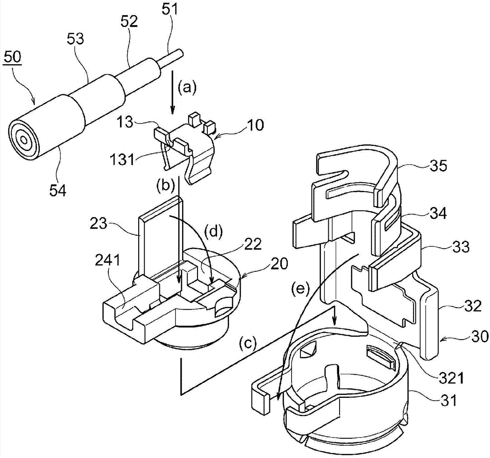
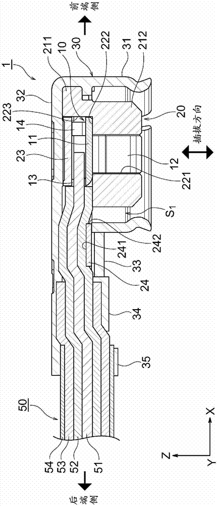
[0024] Figure 1~Figure 3 Is a diagram showing a coaxial connector in this embodiment, Figure 4A~Figure 5 It is a figure which shows the fitting operation of the coaxial connector in this embodiment.

[0025] Such as Figure 1~Figure 3 As shown, the coaxial connector 1 in this embodiment is an L-shaped coaxial connector installed at the end of the coaxial cable 50. Such as Figure 4A , Figure 4B as well as Figure 5 As shown, the coaxial connector 1 can be fitted with, for example, a surface mount type (SMT: Surface Mount Technology) coaxial connector 60 (hereinafter referred to as the target connector 60), and can be used in mobile phones, PDAs (Personal Digital Assistant: personal digital assistant), notebook computers and other portable information processing terminal devices equipped with communication antennas and other electronic equipment. In addition, as the circuit wir...


PUM


Abstract

A coaxial connector includes a contact, a housing, and a ground shell. The contact includes a first wall portion in which an insertion groove into which an inner conductor of a coaxial cable is to be inserted is formed. The housing includes a body portion in which an accommodation hole which accommodates the contact is formed and a middle cover portion which closes the housing hole. A surface on the rear-end side of the middle cover portion and a surface on the rear-end side of the first wall portion substantially overlap with each other in a plan view thereof.

Description

Technical field [0001] The present invention relates to an L-shaped coaxial connector installed on a coaxial cable. [0002] Regarding the designated countries that approve the incorporation based on the reference of the literature, the contents described in Japanese Patent Application No. 2010-76893, which will be filed in Japan on March 30, 2010, are incorporated into this specification by referring to the contents. As part of the description of this manual. Background technique [0003] As an L-shaped coaxial connector, the following connector is known: it has a terminal, an insulator, and an external conductor, the contact part of the terminal is housed in the hollow part of the insulator, and the wiring part of the terminal is placed on both sides of the hollow part Surface, and the middle cover portion of the insulator is curved parallel to the upper surface (for example, refer to Patent Document 1 (particularly paragraphs 0024 to 0026 and figure 2 )). [0004] Patent Documen...

Claims


Application Information

Patent Timeline
Patent Type & Authority Patents(China)
IPC IPC(8): H01R24/38
CPCH01R24/50H01R13/501H01R24/54H01R13/112
Inventor 田口宏行
Owner FUJIKURA LTD
Why Eureka
Try Eureka