Electrical connectors and electrical connector assemblies

An electrical connector and connector technology, applied in the direction of two-part connection device, connection, circuit, etc., can solve the problems of low height of electrical connectors, damage strength, workability of fitting reliability, difficult terminals, etc.

Active Publication Date: 2019-04-30
HIROSE ELECTRIC GROUP
View PDF5 Cites 0 Cited by
  • Summary
  • Abstract
  • Description
  • Claims
  • Application Information

AI Technical Summary

Problems solved by technology

[0006] However, simply reducing the thickness of structural members such as terminals and housings in order to reduce the height of electrical connectors may impair their strength, fitting reliability, workability, etc.
In addition, in the case of a type of connector in which the cable-side connector is brought close to the board-side connector and fitted from above the board-side connector mounted on the circuit board, the contact distance between the terminals at the time of mating needs to be It is difficult to make the terminal smaller by maintaining a certain distance or more and maintaining the reliability of mating

Method used


Image

  • Electrical connectors and electrical connector assemblies
  • Electrical connectors and electrical connector assemblies
  • Electrical connectors and electrical connector assemblies

Examples


Embodiment Construction

[0056] Hereinafter, embodiments of the present invention will be described in detail with reference to the drawings. In addition, in all the drawings for describing the embodiments, the same members are given the same reference numerals in principle, and repeated description thereof will be omitted. In addition, in the following embodiments, when referring to the number of elements (including number, numerical value, amount, range, etc.), except for the case where it is particularly clearly stated and the case where it is clearly limited to a specific number in principle, etc. , is not limited to this specific number, and may be above or below a specific number.

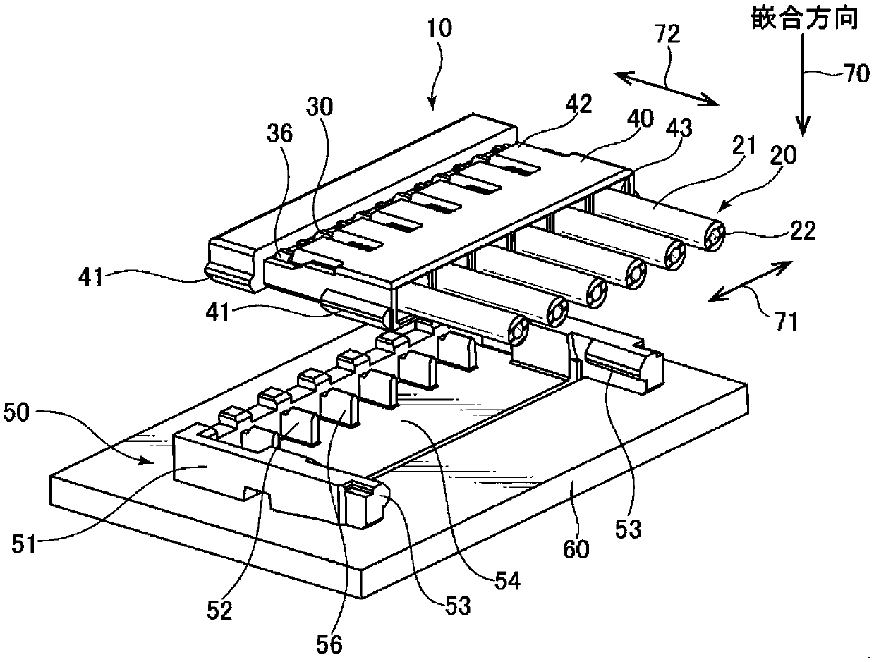
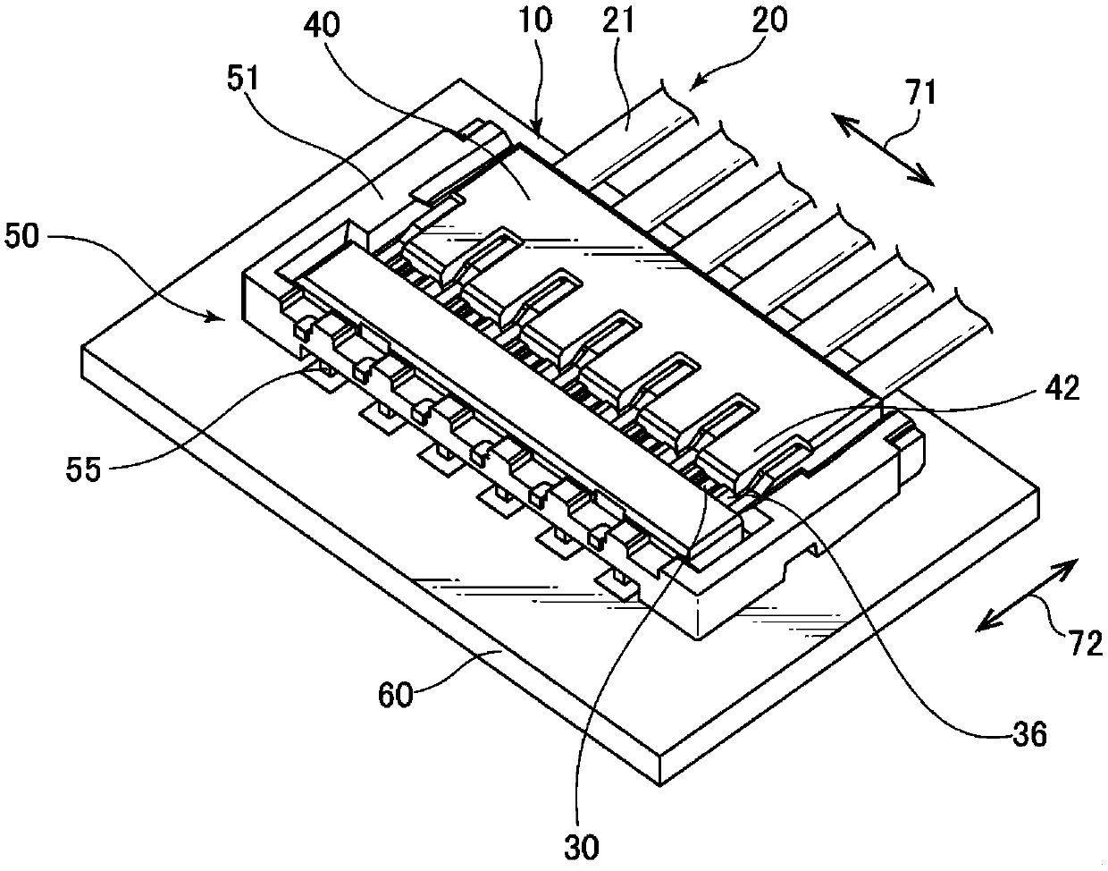
[0057] figure 1 It is a perspective view showing the appearance before fitting of the cable-side connector and the board-side connector according to one embodiment of the present invention. figure 2 It is a perspective view showing the external appearance after fitting of the cable-side connector and the board-sid...


PUM


Abstract

The present invention provides a technique in which the strength, the mating reliability, the workability, and the like can be maintained in the electrical connector and can achieve low height. The electrical connector of the present invention comprises a housing (30) connected to a cable (20) and a housing (30) connected to a cable (20); the terminal (30) comprising: a crimping portion (31, 32) (33) which is substantially U-shaped and has a flat surface in a direction (71) perpendicular to the fitting direction, and the elastic portion (33) has a flat surface (34) extending from both outer sides of the elastic portion (33) in a direction opposite to the fitting direction of the elastic portion (33), and an erect portion (34) and a contact portion (35) located at an inner end of the elastic portion (33); the elastic portion (33) has a direction in a direction perpendicular to the fitting direction (71) and the contact portion (35) is configured to sandwich the terminals of the opposite side connector on both sides of the inner side of the elastic portion (33) when fitting with the counterpart connector.

Description

technical field [0001] The present invention relates to an electrical connector, and more particularly to a thin electrical connector connected to a connector mounted on a surface of a printed circuit board or the like. Background technique [0002] Conventionally, in order to connect electric wires such as cables to circuit boards such as printed circuit boards, electrical connectors for electrically connecting cables and wiring on the boards have been used. In such an electrical connector, one connector (board-side connector) is mounted on the circuit board, and the other connector (cable-side connector) is connected to the cable. By fitting these connectors, the cable and the circuit board The signal line is electrically connected. [0003] Moreover, as a technique related to such an electrical connector, the technique described in patent document 1 etc. are mentioned, for example. The electrical connector described in Patent Document 1 is a crimp-type electrical connec...

Claims


Application Information

Patent Timeline
Patent Type & Authority Patents(China)
IPC IPC(8): H01R12/71H01R13/24H01R24/00
CPCH01R12/712H01R13/24H01R24/00H01R13/11H01R13/46
Inventor 吉沢俊彦
Owner HIROSE ELECTRIC GROUP
Why Eureka
Try Eureka