Coil device

A coil device, wire technology, applied in the direction of transformer/inductor coil/winding/connection, electrical components, transformer/inductor components, etc., can solve the problem of low degree of design freedom

Active Publication Date: 2020-07-07
TDK CORPARATION
View PDF5 Cites 0 Cited by
  • Summary
  • Abstract
  • Description
  • Claims
  • Application Information

AI Technical Summary

Problems solved by technology

However, in the coil device of Patent Document 1, since the terminal block and the bobbin are integrally formed, when the specifications of the terminal block are changed, the entire bobbin frame must be remade, and the degree of freedom in design is low.

Method used


Image

  • Coil device
  • Coil device
  • Coil device

Examples


Embodiment Construction

[0044] Hereinafter, the present invention will be described based on the embodiments shown in the drawings.

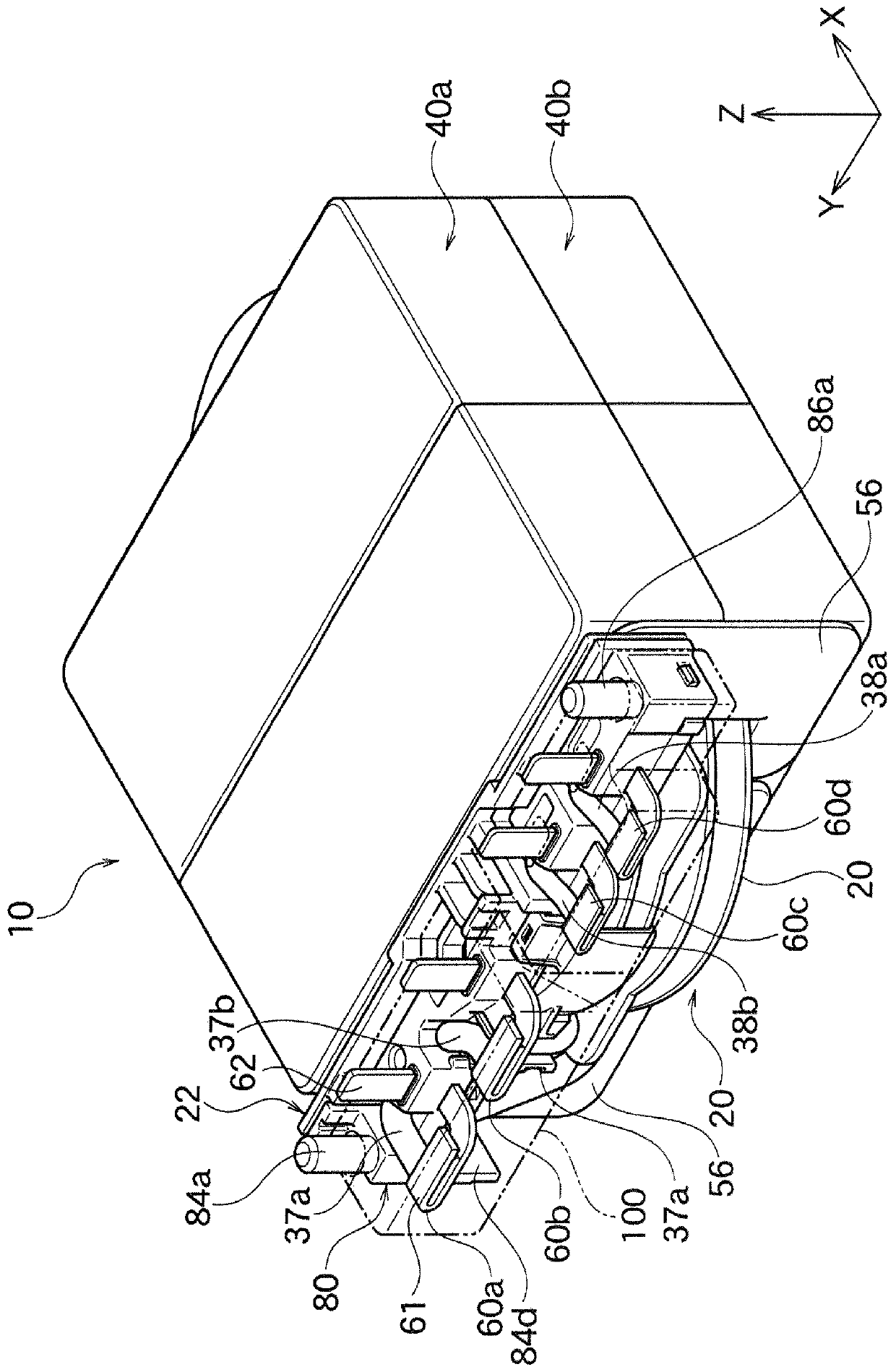
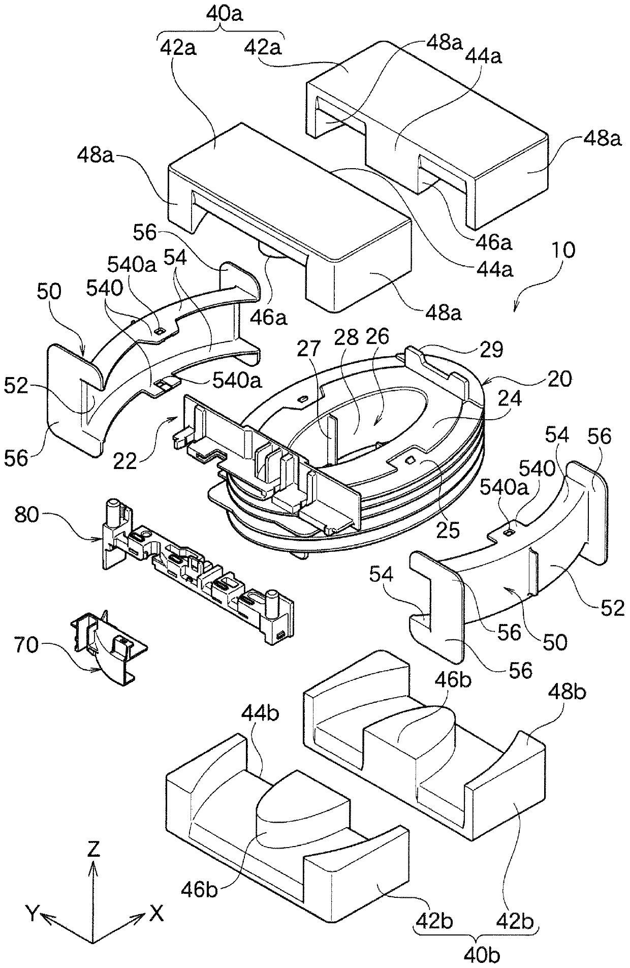
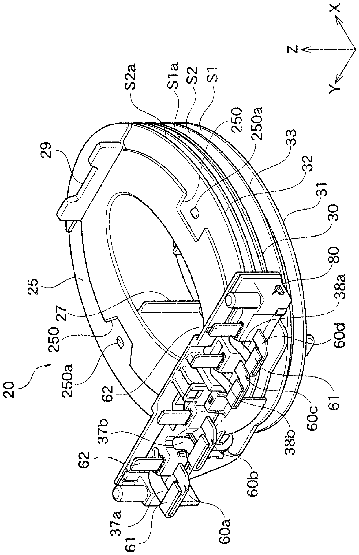
[0045] figure 1 The shown transformer 10 as the coil device of this embodiment is used for, for example, EV (Electric Vehicle: Electric Vehicle), PHV (Plug-in Hybrid Vehicle: Plug-in Hybrid Electric Vehicle), or commuter (vehicle) vehicle Chargers, or power supply circuits of household or industrial electrical equipment, or power supply circuits of computer equipment, etc. Such as figure 2 As shown, the transformer 10 has a bobbin 20 , magnetic cores (split cores) 40 a and 40 b , and a terminal block 80 .

[0046] In addition, in the drawings, the X-axis, Y-axis, and Z-axis are perpendicular to each other, the X-axis corresponds to the longitudinal direction of the bobbin 20, and the Y-axis corresponds to the pair of split cores 42a, 42a or the pair of split cores 42b, 42b. The direction of the dividing line is roughly the same. The direction of the dividing line ...


PUM


Abstract

The present invention provides a coil device with a high degree of design freedom. The coil device (10) has: a bobbin (20) on which a first lead (37) constituting a first coil part (35) and a second lead (38) constituting a second coil part (36) are wound; a terminal block (80), which leads out a pair of first lead parts (37a, 37b) of the first lead (37) and a pair of the second lead parts (38a, 38b) of the second lead (38). The terminal block (80) and the bobbin (20) are formed as separate bodies, and are installed on a terminal block connection part (22) of the bobbin (20) from a direction substantially perpendicular to the winding axis Z of the bobbin.

Description

technical field [0001] The invention relates to a coil arrangement which is preferably used as, for example, a transformer or the like. Background technique [0002] Patent Document 1 discloses a coil device including a terminal block from which a pair of lead wire portions of lead wires are drawn out. However, in the coil device of Patent Document 1, since the terminal block and the bobbin are integrally formed, when the specifications of the terminal block are changed, the entire bobbin frame must be newly produced, and the degree of freedom in design is low. [0003] prior art literature [0004] patent documents [0005] Patent Document 1: Japanese Patent Laid-Open No. 2013-254890 Contents of the invention [0006] The problem to be solved by the invention [0007] The present invention has been made in view of such circumstances, and an object of the present invention is to provide a coil device having a high degree of freedom in design. [0008] Technical soluti...

Claims


Application Information

Patent Timeline
Patent Type & Authority Applications(China)
IPC IPC(8): H01F27/28H01F27/29H01F27/30
CPCH01F27/29H01F27/306H01F27/28H01F27/2823H01F27/2828
Inventor 熊谷胜佐佐木胜一岩仓正明
Owner TDK CORPARATION
Why Eureka
Try Eureka