Flexible Spring Mounting Device

An installation device and a flexible spring technology, applied in metal processing equipment, metal processing, manufacturing tools, etc., can solve problems such as low spring installation work efficiency, and achieve the effect of reducing labor workload, improving work efficiency, and shortening installation time.

Inactive Publication Date: 2019-03-08
重庆市大足区川江金属制品厂
View PDF5 Cites 0 Cited by
  • Summary
  • Abstract
  • Description
  • Claims
  • Application Information

AI Technical Summary

Problems solved by technology

[0004] The present invention intends to provide a flexible spring installation device to solve the problem of low efficiency of spring installation work in the above-mentioned prior art

Method used


Image

  • Flexible Spring Mounting Device
  • Flexible Spring Mounting Device
  • Flexible Spring Mounting Device

Examples


Embodiment 1

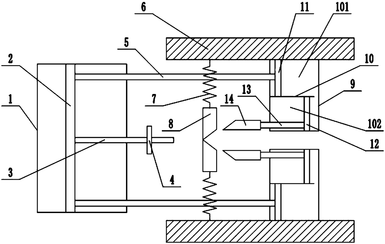
[0019] Such as figure 1 A flexible spring mounting device shown includes a first cylinder 1 , a fixed wall 6 , a wedge-shaped stop 8 and a wedge-shaped push block 14 . First cylinder 1 is provided with piston 2, and the right side of piston 2 is connected with spring guide rod 3 and two piston rods 5, and two piston rods 5 are positioned at the both sides of spring guide rod 3 respectively; Spring guide rod 3 is telescopic rod, And spring guide rod 3 is provided with baffle plate 4; A pair of fixed wall 6 is arranged on the both sides of spring guide rod 3 with spring guide rod 3 as central axis symmetry, and each side fixed wall 6 is provided with spring successively from left to right. 7 and the second cylinder 9; the spring 7 links to each other with the wedge-shaped block 8, and the wedge-shaped block 8 is provided with an arc groove 81 and a slideway 82, and the radius of the arc groove 81 is greater than or equal to the radius of the spring guide rod 3, Two wedge-shaped...

Embodiment 2

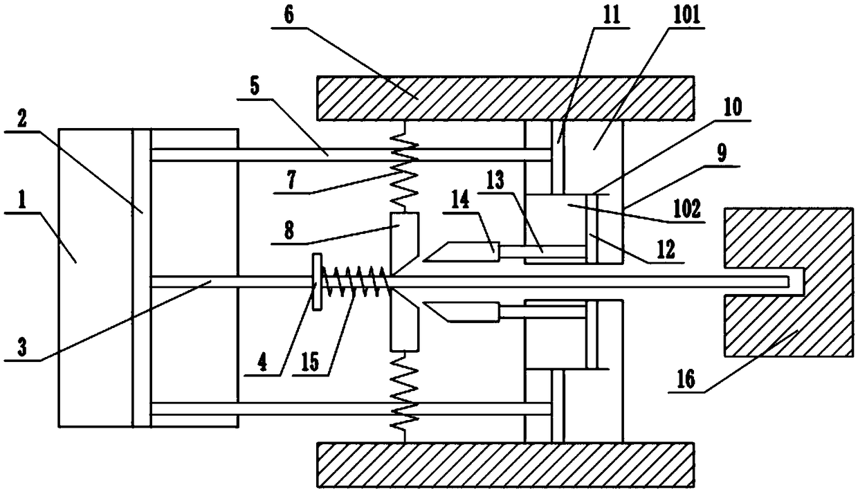
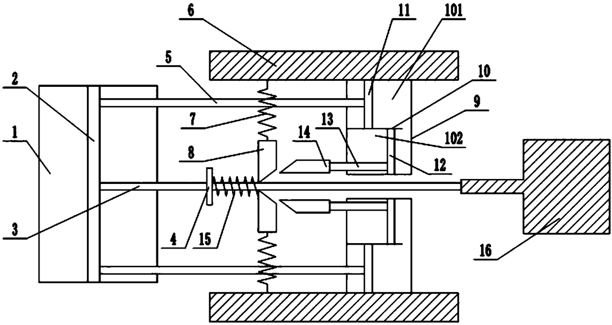
[0022] The difference between this embodiment and Embodiment 1 is that: image 3 As shown, when the flexible spring 15 is installed on the shaft of the workpiece 16, the rightmost end of the spring guide rod 3 is against the shaft of the workpiece 16, and when the first cylinder 1 pushes the spring guide rod 3, due to the front end of the spring guide rod 3 and the When the shafts are offset, the spring guide rod 3 shrinks, so that the stroke path of the flexible spring 15 is shortened, and the installation time of the flexible spring 15 is shortened.


PUM


Abstract

The invention relates to the technical field of automobile part assembly tools, in particular to a flexible spring mounting device. The device comprises a first air cylinder, a pair of fixed walls, apair of wedge-shaped check blocks and a pair of wedge-shaped push blocks. The first air cylinder is provided with a piston, and a spring guide rod and two piston rods are connected to the piston. Thespring guide rod is a telescopic rod and is provided with a baffle. The pair of fixed walls is arranged on the two sides of the spring guide rod, and a spring and a second air cylinder are arranged onthe fixed wall on each side. Each spring is connected with one end of the corresponding wedge-shaped check block, and the other ends of the two wedge-shaped check blocks abut against each other to form a wedge-shaped portion. A partition plate is arranged in each second air cylinder and divides the interior of the corresponding second air cylinder into two communicating chambers. A first piston and a second piston are arranged in the two chambers of each second air cylinder correspondingly, each first piston is connected with the corresponding piston rod, and each second piton is connected with the corresponding wedge-shaped push block. According to the flexible spring mounting device, manpower can be replaced for mounting a flexible spring, the work efficiency can be improved, and the situation that the hands of operation personnel are hurt due to overwork can be avoided.

Description

technical field [0001] The invention relates to the technical field of assembly tools for auto parts, and specifically discloses a flexible spring installation device. Background technique [0002] Springs are used in a wide range of fields, including transportation industries such as automobiles, motorcycles, diesel engines, and railways, as well as daily necessities, hardware, instruments, and electronic and electrical springs. At present, the transportation industry is the most important and promising market in the field of spring applications. [0003] With the development of the economy and the improvement of people's living standards, people's demand for cars is also increasing. Therefore, the automobile manufacturing industry is also developing and improving. In the process of automobile production and manufacturing, for the installation of springs in auto parts, the springs are mainly assembled by hand. For example, when installing a contraction spring in a clutch,...

Claims


Application Information

Patent Timeline
Patent Type & Authority Patents(China)
IPC IPC(8): B23P19/04
CPCB23P19/048
Inventor 孙可均
Owner 重庆市大足区川江金属制品厂
Why Eureka
Try Eureka