Unhooking device

A half-hook and hook technology, applied in the field of decoupling devices, can solve problems such as low operating efficiency, inability to reuse, and inability to achieve instant decoupling

Pending Publication Date: 2018-04-10
TIDFORE HEAVY IND
View PDF0 Cites 4 Cited by
  • Summary
  • Abstract
  • Description
  • Claims
  • Application Information

AI Technical Summary

Problems solved by technology

The lifting efficiency of the above method is low. During the lifting process of the goods, a special person is required to untie the cable. When using manual work to untwist, the risk of instability of the goods is high, and the operation efficiency is low.
On the other hand, the use of existing hooks, wire cables to transfer goods or installation components needs to be placed slowly and unbuckled only when the safety of the unclamping personnel is ensured. The safety factor is greatly affected by the limited vision of the crane operator.
[0003] In order to solve the above technical problems, in the prior art, technicians have designed automatic uncoupling devices, which are commonly used in the following three types. The first one is to use a wire rope to pull and release. This method cannot meet the requirements of release at any position and at any time, and There is a large error in the release point, and there is no automatic control capability; the second is to use the cylinder movement to drive the decoupling release. This method is relatively safe and reliable, but due to the delay caused by the push rod or cylinder action, the effect of instantaneous decoupling cannot be achieved; The third method is to use explosive bolts. This method decouples quickly, but cannot be reused, and it is difficult to achieve synchronous control of multiple explosive bolts during the decoupling process.

Method used


Image

  • Unhooking device
  • Unhooking device
  • Unhooking device

Examples


Embodiment Construction

[0032] The present invention will be described in detail below in conjunction with the accompanying drawings. The description in this part is only exemplary and explanatory, and should not have any limiting effect on the protection scope of the present invention. In addition, those skilled in the art can make corresponding combinations of features in the embodiments in this document and in different embodiments according to the descriptions in this document.

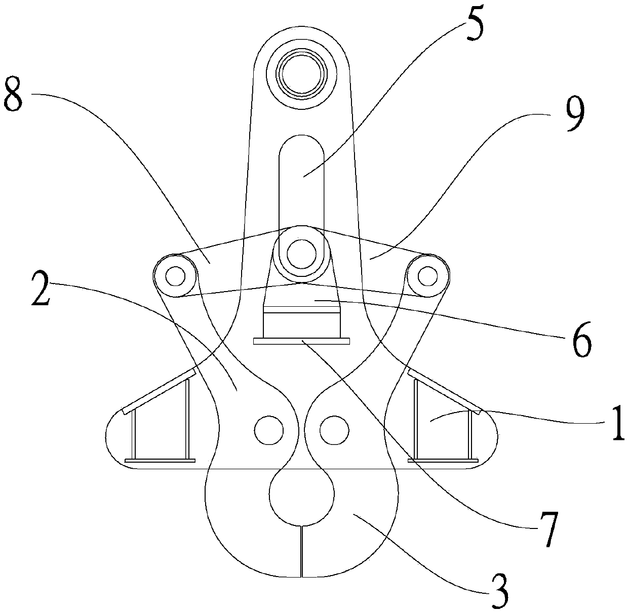
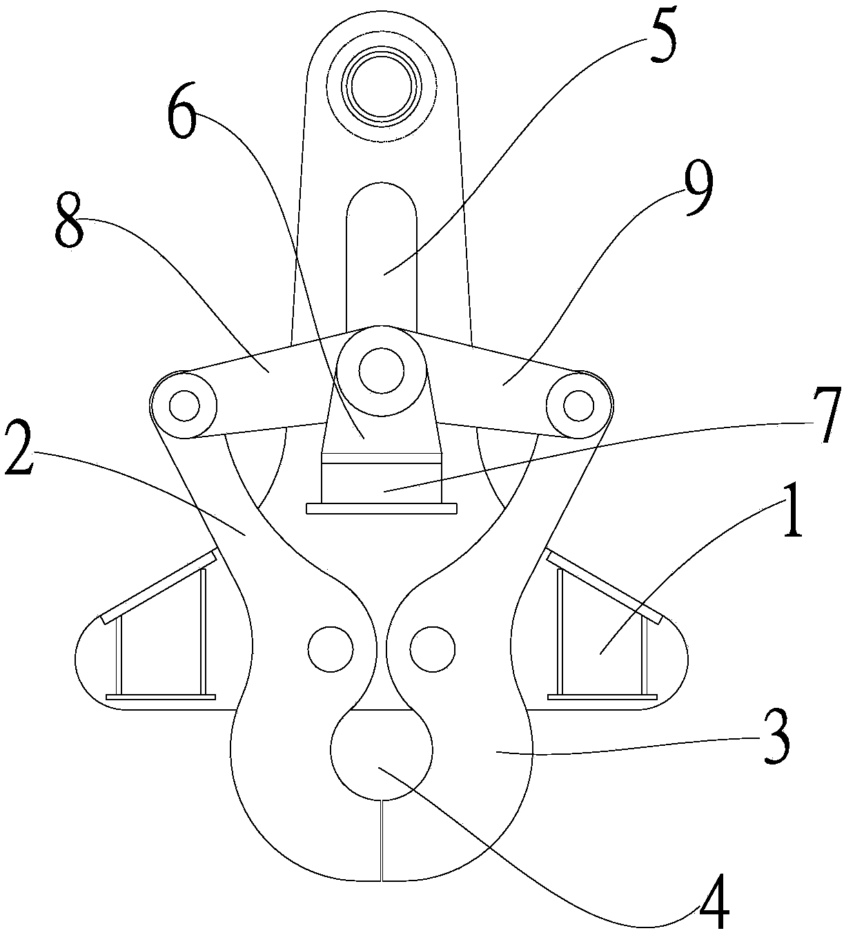
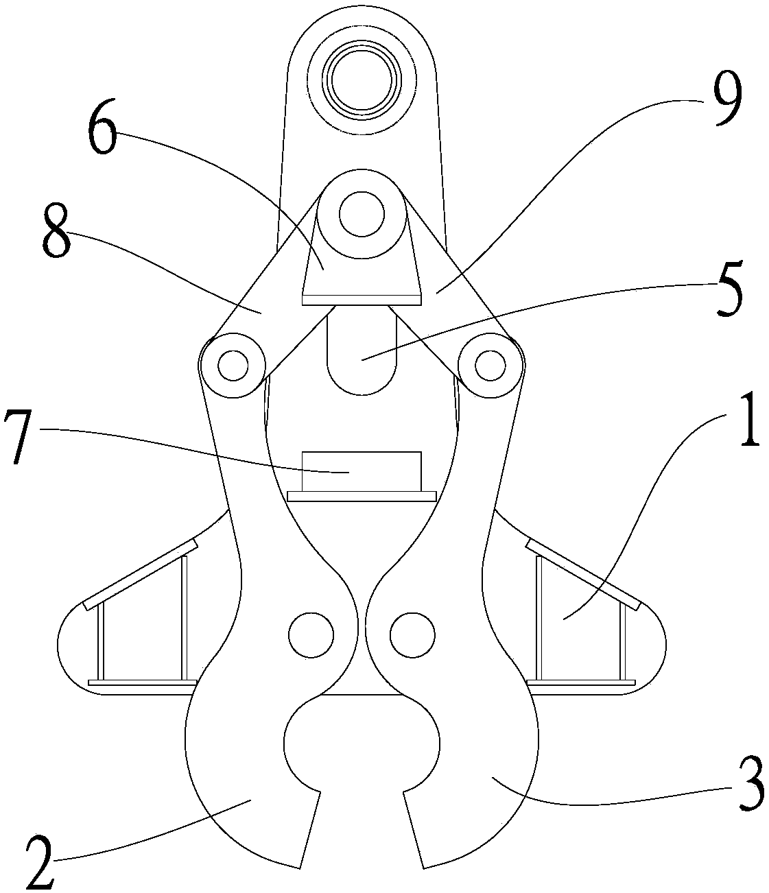
[0033] Embodiments of the present invention are as follows, with reference to Figure 1~3 , a decoupling device, comprising a fixing part 1 and a hook, the hook is arranged on the fixing part 1, the hook includes a first half hook 2 and a second half hook 3, the first half hook 2 and the second half hook The two half-hooks 3 can be closed to form a hanging hole 4, at least the first half-hook 2 is hinged on the fixing part 1, and the fixing part 1 is provided with a guide rail 5 arranged vertically, and the guide rail 5 ...


PUM


Abstract

The invention relates to a decoupling device, which includes a fixing piece and a hook. The hook includes a first half hook and a second half hook. At least the first half hook is hinged on the fixing piece. The fixing piece is provided with a guide rail arranged vertically. There is an adjustment piece, the adjustment piece is connected with the first half hook through the first connecting rod, the two ends of the first connecting rod are respectively hinged with the upper end of the first half hook and the adjustment piece, and the first half The hook rotates along its hinge point on the fixing part to realize the opening and closing of the lifting hole, and the adjusting part is fixed at the preset position of the guide rail by the positioning part. The invention is simple in structure, small in size and low in cost, and fully utilizes the principle of leverage to realize the carrying and unhooking of the hook, which saves labor and has high reliability, direct action, good unhooking effect, and can achieve the effect of instant unhooking and opening without action delay , The loading and unloading position is accurate, and it can realize high-speed decoupling and release, especially suitable for the lifting of cargo with a large load and carried at a relatively fast speed.

Description

technical field [0001] The invention belongs to the technical field of hoisting equipment, and in particular relates to a decoupling device. Background technique [0002] In the current field of lifting equipment, the commonly used equipment includes hooks, steel wire cable buckles, etc. The above-mentioned lifting equipment usually uses one person to connect the packaged goods with the hook of the crane using steel wire cables or nylon cables, and the crane lifts and transfers the goods. After arriving at the designated transportation point, another person will untie the cable, thus completing a lifting cycle. The lifting efficiency of the above-mentioned method is low. During the lifting process of the goods, a special person is required to untie the cable. When unclasping by manual work, the risk of instability of the goods is relatively high, and the operation efficiency is low. On the other hand, the use of existing hooks, wire cables to transfer goods or installation ...

Claims


Application Information

Patent Timeline
Patent Type & Authority Applications(China)
IPC IPC(8): B66C1/38
CPCB66C1/38
Inventor 曾锋段能林顺才陈婷朱强波姚艺武刘阳样
Owner TIDFORE HEAVY IND
Why Eureka
Try Eureka