Hasp with self-lock and buckle ring anti-twisting structure

An anti-twist and buckle technology, which is applied in the direction of mechanical equipment and fixing devices, can solve the problems of positioning pin shaking or misalignment, potential safety hazards, and easy automatic bounce, so as to prevent free rotation, improve service life, and reduce potential safety hazards Effect

Inactive Publication Date: 2018-05-01
荣成康派斯新能源车辆股份有限公司
View PDF0 Cites 10 Cited by
  • Summary
  • Abstract
  • Description
  • Claims
  • Application Information

AI Technical Summary

Problems solved by technology

[0003] At present, the commonly used buckles often have the following problems when they are applied: first, when the buckle is fastened but not locked, it is easy to bounce off automatically under a slight external force impact, and there are certain safety hazards; The buckle is adjusted to an appropriate tension position through the rotation of the screw rod on the buckle ring, but the screw rod of the buckle ring is prone to loosening when it cooperates with the central shaft, and the automatic rotation changes the adjusted position, so every time the buckle is closed When buckling, it is necessary to re-rotate the buckle to adjust the tension force, which brings unnecessary trouble to the assembly
At the same time, the existing adjustable hasp usually only has one fixed keyhole, and the pull ring is fixed through a positioning pin through the fixed keyhole. It is easy to cause the positioning pin to shake or misalign at the keyhole, and it is easy to cause it to fall off

Method used


Image

  • Hasp with self-lock and buckle ring anti-twisting structure
  • Hasp with self-lock and buckle ring anti-twisting structure
  • Hasp with self-lock and buckle ring anti-twisting structure

Examples


Embodiment Construction

[0021] In order to clearly illustrate the technical features of this solution, the present invention will be described in detail below through specific implementation modes and in conjunction with the accompanying drawings.

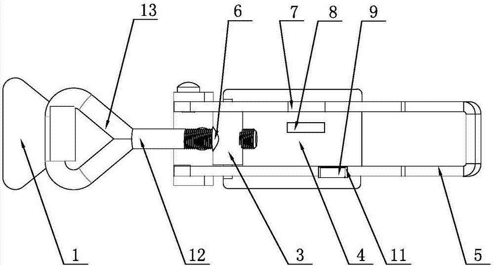
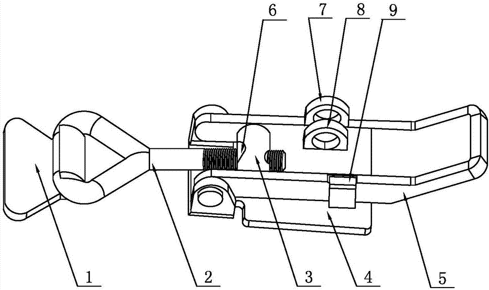
[0022] as attached Figure 1-3 As shown, the buckle with self-locking and buckle anti-twist structure includes a hook 1 and a lock body that is movably locked with the hook; the lock body includes a base 4, and a pull ring 5 is hinged on the base 4. A central shaft 3 is fixedly connected to the inner side of the draw ring, and a threaded hole is provided in the middle of the central shaft 3, and the central shaft 3 is threaded with a buckle 2 through the threaded hole; The first keyhole 7 is provided with a second keyhole 8 corresponding to the first keyhole 7 on the base inside the draw ring, and the distance between the first keyhole 7 and the second keyhole 8 is smaller than that of the second keyhole 8 and the second keyhole 8. Spacing on the other s...


PUM


Abstract

The invention relates to the field of motor homes, in particular to a hasp with a self-lock and buckle ring anti-twisting structure. The hasp comprises a hook and a buckle body movably locked to the hook. The buckle body comprises a base, a pull ring is hinged to the base, a center shaft is fixedly connected to the inner side of the pull ring, a threaded hole formed in a penetration manner is formed in the middle portion of the center shaft, and the center shaft is in threaded connection with a buckle ring through the threaded hole. The part, on one side, of the pull ring is provided with a first lock hole, and a second lock hole is formed in the part, in the direction perpendicular to the pull ring rotating direction, of the base in a flush manner. The distance between the first lock holeand the second lock hole is smaller than the distance between the second lock hole and the part, on the other side, of the pull ring. A supporting block is arranged on the outer side of the base, andan elastic stop sheet is arranged at the top end of the supporting block. An injection molding body with which unnecessary space is filled is arranged on the inner side of an inner thread of the center shaft, wherein the unnecessary space is obtained after the buckle ring and the center shaft are in threaded fit. The hasp with the self-lock and buckle ring anti-twisting structure can prevent positioning pin swinging and disengaging in the vehicle running process, and the product safety is improved.

Description

Technical field: [0001] The invention relates to the field of caravan technology, in particular to a hasp with self-locking and anti-rotation structure of buckle ring. Background technique: [0002] A buckle refers to an object that is lapped between two objects for fastening. Buckles are generally metal parts, and their quality and stability directly affect the stability of use. At present, hasp is widely used in car compartment, truck compartment and electric tricycle rear compartment. In order to improve the safety during driving, the hasp used in the automotive field should have two functions of lockable and anti-twist. [0003] At present, the commonly used buckles often have the following problems when they are applied: first, when the buckle is fastened but not locked, it is easy to bounce off automatically under a slight external force impact, and there are certain safety hazards; The buckle is adjusted to an appropriate tension position through the rotation of th...

Claims


Application Information

Patent Timeline
Patent Type & Authority Applications(China)
IPC IPC(8): F16B1/02
CPCF16B1/02
Inventor 王位元
Owner 荣成康派斯新能源车辆股份有限公司
Why Eureka
Try Eureka