
Overhead optical cable for splicing

A technology for overhead optical cables and connecting parts, which is applied in the field of aerial optical cables for splicing, which can solve the problems of increasing splicing points, increasing the complexity of splicing loss, construction difficulty, and difficult opening and stripping of optical cables, and achieves reduced outer diameter, light weight, and convenient construction Effect

Inactive Publication Date: 2018-06-05
NANJING WASIN FUJIKURA OPTICAL COMM LTD
View PDF11 Cites 1 Cited by
  • Summary
  • Abstract
  • Description
  • Claims
  • Application Information

AI Technical Summary

Problems solved by technology

[0002] The existing overhead optical cables are basically stripped at the ends, but in actual construction, the junction points such as the relay position are often uncertain. The traditional construction method needs to cut the optical cable and then strip it, but it does not need to be completely cut in some positions. All optical fibers, which increase the splicing point, thereby increasing the splicing loss and the complexity of construction
And traditional optical cables are generally difficult to perform stripping and splicing operations in the air

Method used


Image

  • Overhead optical cable for splicing

Examples


Embodiment Construction

[0021] The present invention will be further described below in conjunction with the accompanying drawings.

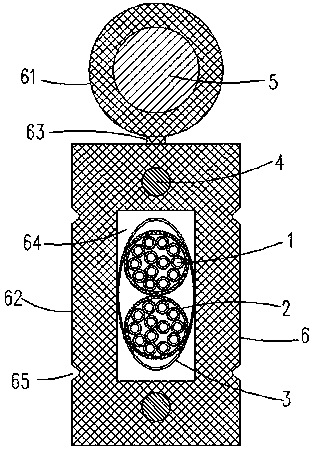
[0022] Such as figure 1 As shown, the present invention is a kind of aerial optical cable for splicing, including colored optical fiber 1, microtube 2, wrapping tape 3, reinforcement 4, reinforcement 5 and sheath 6, and sheath 6 includes integrally formed round sleeve part 61, The rectangular sleeve part 62 and the connecting part 63, the connecting part 63 is placed between the circular sleeve part 61 and the rectangular sleeve part 62, and a first wrapping cavity is provided in the axial direction (ie, the length direction) of the circular sleeve part 61. A second wrapping cavity 64 is provided in the center direction of the sleeve portion 62 . The microtubes 2 are wrapped on the colored optical fiber 1 to form a micro-tuft unit, and the two micro-tuft units are arranged parallel to each other. The wrapping tape 3 is wrapped around the two micro-tuft units and passe...


PUM


Abstract

The invention discloses an overhead optical cable for splicing. A sheath comprises a circular sleeve part, a rectangular sleeve part and a connecting part which are molded integrally. A micro-tube packages a coloring optical fiber and forms a micro-cluster pipe unit. Two micro-cluster pipe units parallelly penetrate a second packaging chamber. A packaging pipe wraps the two micro-cluster pipe units. A reinforcing member is arranged in a first packaging chamber of the circular sleeve part. Two reinforcements penetrate through the rectangular sleeve part. Furthermore the two reinforcements are symmetrically arranged at the upper side and the lower side of the second packaging chamber. The left side wall and the right side wall of the rectangular sleeve part are respectively provided with twostripping grooves symmetrically. Two stripping grooves on the left side wall of the rectangular sleeve part are arranged symmetrically with the two stripping grooves on the right side wall. Two stripping grooves on each side wall of the rectangular sleeve part are correspondingly arranged outside the two micro-cluster pipe units, and are correspondingly arranged at inside of the upper side wall and the lower side wall of the second packaging chamber. The overhead optical cable is advantages in that a compact structure is realized; a multi-core micro-pipe structure is utilized for reducing thedimension of the cable as possible, reducing the external diameter of the cable, reducing weight of the cable and realizing easy stripping.

Description

Technical field: [0001] The invention relates to an overhead optical cable for digging. Background technique: [0002] The existing overhead optical cables are basically stripped at the ends, but in actual construction, the junction points such as the relay position are often uncertain. The traditional construction method needs to cut the optical cable and then strip it, but it does not need to be completely cut in some positions. For all optical fibers, this increases the splicing points, thereby increasing the splicing loss and the complexity of construction. Moreover, it is generally difficult to perform stripping and splicing operations in the air with traditional optical cables. Therefore, it is necessary to improve the prior art to solve the deficiencies of the prior art. Invention content: [0003] The present invention provides an aerial optical cable for drawing and splicing in order to solve the above-mentioned problems in the prior art. [0004] The techn...

Claims


Application Information

Patent Timeline
Patent Type & Authority Applications(China)
IPC IPC(8): G02B6/44
CPCG02B6/443G02B6/4433G02B6/4439G02B6/4459
Inventor 吴昌亮
Owner NANJING WASIN FUJIKURA OPTICAL COMM LTD
Learn More