Home television antenna

A home TV and antenna technology, which is applied in the field of home TV antennas, can solve the problems that the receiving distance cannot be controlled at will, and the internal circuit structure is complex, etc., and achieve the effect of simple line diagram, good reception effect and strong reception signal

Pending Publication Date: 2018-06-05
吴芳
View PDF6 Cites 0 Cited by
  • Summary
  • Abstract
  • Description
  • Claims
  • Application Information

AI Technical Summary

Problems solved by technology

[0004] However, the antenna for receiving high-definition digital television signals of the caravan and household televisions disclosed in this utility model has a complex internal circuit structure, and the receiving distance cannot be controlled arbitrarily.

Method used


Image

  • Home television antenna
  • Home television antenna
  • Home television antenna

Examples


Embodiment Construction

[0025] In order to make the object, technical solution and advantages of the present invention clearer, the present invention will be further described in detail below in conjunction with the accompanying drawings and embodiments. It should be understood that the specific embodiments described here are only used to explain the present invention, not to limit the present invention.

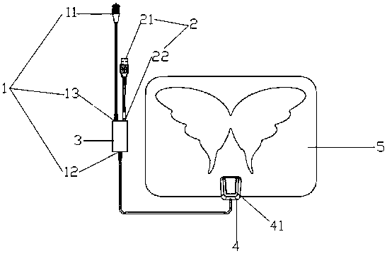
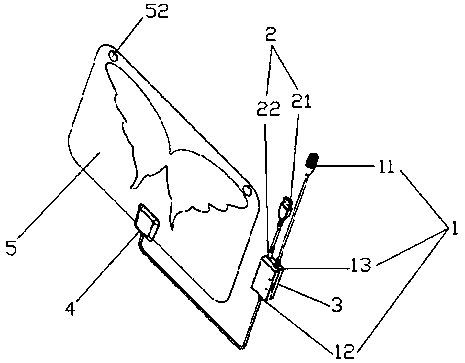
[0026] see Figure 1-3 As shown, the present invention provides a household TV antenna, which includes a signal transmission device 1, a power supply device 2, an antenna amplification device 3, an antenna fixing casing 4, an antenna main board 5, a signal transmission device 1 and an antenna amplification device 3. Electric connection, the power supply device 2 is electrically connected with the antenna amplifier 3, the antenna fixing case 4 is fixed on the antenna main board 5, the antenna 51 is arranged inside the antenna main board 5, and the antenna 51 is connected and fixed on the antenna mai...


PUM


Abstract

The invention discloses a home television antenna. The home television antenna comprises a signal transmission device, a power supply device, an antenna amplifying device, an antenna fixing enclosureand an antenna main board, wherein the signal transmission device is electrically connected with the antenna amplifying device; the power supply device is electrically connected with the antenna amplifying device; the antenna fixing enclosure is fixed on the antenna main board; an antenna is arranged in the antenna main board and is fixedly connected in the antenna main board by the antenna fixingenclosure; the antenna is electrically connected with the antenna amplifying device by the signal transmission device. According to the home television antenna, by adopting a special antenna structure, line graphs are simplified, and stronger receiving signal and better receiving effect are realized; the defects of the prior art are overcome; by arranging the structure of the antenna amplifying device, the receiving distance can be controlled by a switch.

Description

technical field [0001] The invention belongs to the field of antennas, in particular to a household TV antenna. Background technique [0002] An antenna is a transformer that transforms a guided wave propagating on a transmission line into an electromagnetic wave propagating in an unbounded medium (usually free space), or vice versa. The signal reception of the TV needs to be completed by means of an antenna. However, the TV antenna publicly used in the prior art has many defects, the most important being that the receiving signal is not strong and the receiving effect is not good. [0003] The utility model application number is 201520066548.6, which discloses a high-definition digital TV signal receiving antenna for RVs and home TVs, which includes an antenna body, an active receiving signal amplifier circuit, a 5V power supply board, a transmission line and a connector that are electrically connected in sequence , can receive digital TV signals in the full frequency band...

Claims


Application Information

Patent Timeline
Patent Type & Authority Applications(China)
IPC IPC(8): H01Q1/12H01Q1/36H01Q1/50H01Q23/00
CPCH01Q1/12H01Q1/36H01Q1/50H01Q23/00
Inventor 吴芳
Owner 吴芳
Why Eureka
Try Eureka