

Sealing and locating clamp of blind cover of metal blade
A technology for positioning fixtures and blind covers, which is applied in the direction of manufacturing tools, workpiece clamping devices, etc.
Inactive Publication Date: 2018-06-12
JIANGXI CHANGHE AVIATION IND
View PDF4 Cites 0 Cited by
- Summary
- Abstract
- Description
- Claims
- Application Information
AI Technical Summary
Problems solved by technology
[0003] The invention mainly solves the problem of rapid positioning in the sealing process of the main blade blind cover
Method used
View moreImage
Smart ImageViewing Examples

Examples
Embodiment Construction
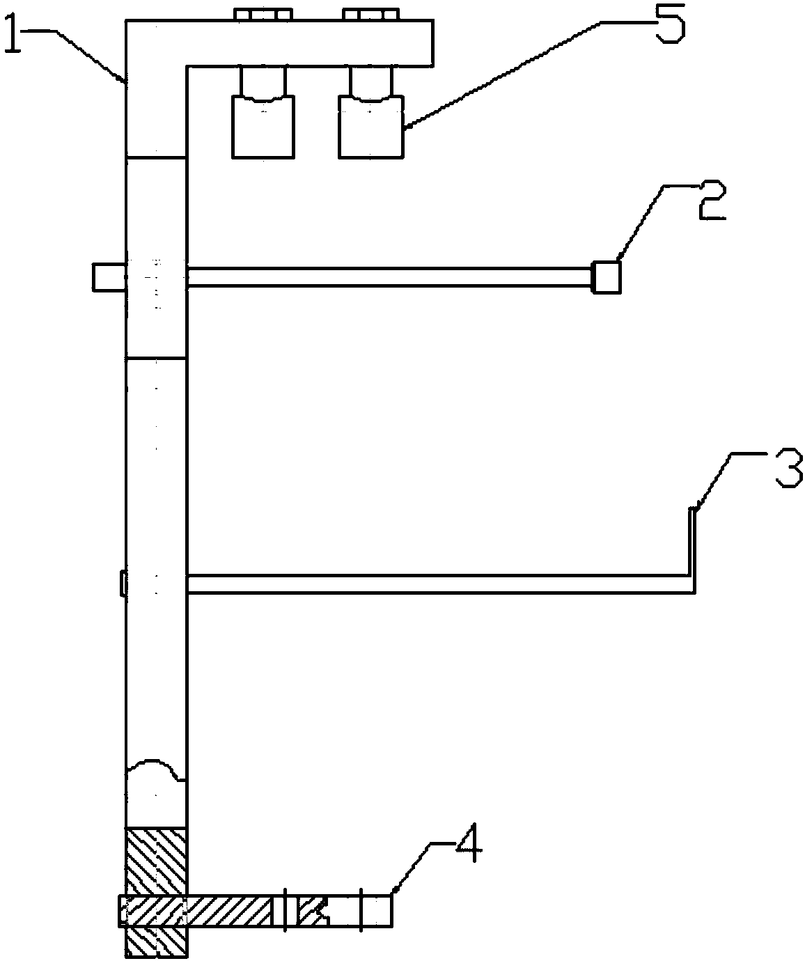
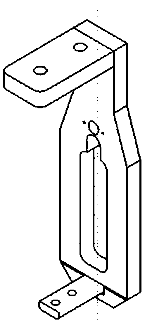
[0012] The present invention will be described in further detail below. refer to Figure 1-2 , in the sealing process of the blind cover, first put the blind cover into the inner cavity of the girder, install the positioning frame 1 on the tip of the girder, specifically, connect the tip of the girder and the fixing plate 4 through nuts, bolts, washers and washers The girders are connected, and then the girder leading edge adjusting device 5 is tightened to press the girder leading edge and keep close to it, then the pull rod 3 is screwed to the blind cap, and then the push rod 2 is used to push the blind cap to the set position.
Login to View More PUM
 Abstract
The invention belongs to the field of helicopter blade assembling, and particularly relates to a sealing and locating clamp of a blind cover of a metal blade. Sealing of the blind cover at the tip ofthe main blade is an important link in the assembling process of the main blade, whether the blind cover is assembled in place or not directly affects whether an inner cavity of a crossbeam is air leakage or not, and the link is a key process in the blade assembling process. Sealing and positioning of the blind cover is very difficult. The sealing and locating clamp comprises a positioning frame,a jacking rod, a pull rod, a fixing plate and a crossbeam front-edge adjusting device, the lower end of the frame is the fixing plate which is connected with the crossbeam tip through bolts, the crossbeam front-edge adjusting device is mounted at the upper end of the frame through a thread and abuts against the crossbeam tip, and the positioning frame is provided with a jacking rod hole and a pullrod hole which communicate with a crossbeam mold cavity. The labor intensity of workers can be reduced, and the working efficiency is improved.
Description
technical field [0001] The invention belongs to the field of helicopter blade assembly, and in particular relates to a metal blade blind cover sealing and positioning fixture. Background technique [0002] The sealing of the blind cover at the tip of the main blade is an important part in the assembly process of the main blade. Whether the blind cover is assembled in place directly affects whether there is air leakage in the inner cavity of the girder, and is a key process in the assembly process of the blade. The sealing and positioning of the blind cover is very difficult. During the assembly process, it is necessary to ensure the assembly clearance and meet the requirements of the profile of the girder. Therefore, a special positioning fixture is required during the assembly process. Only through this positioning fixture can rapid positioning be achieved. And adjust the position of the blind cover for sealing assembly. Contents of the invention [0003] The invention m...
Claims
Login to View More Application Information
Patent Timeline
 IPC IPC(8): B25B11/02
CPCB25B11/02
Inventor杨燊刘洋许莎莎
OwnerJIANGXI CHANGHE AVIATION IND